Fixed Link
The dialog has five tabs (six if you have the Traffic Module enabled).
The first two tabs define the start and end points of the Link. The next two define the parameters associate with the link in the both directions, and the final tab is labelled ‘Advanced’.
Start & End Stations
The Start Tab of the Fixed Link dialog is shown below.
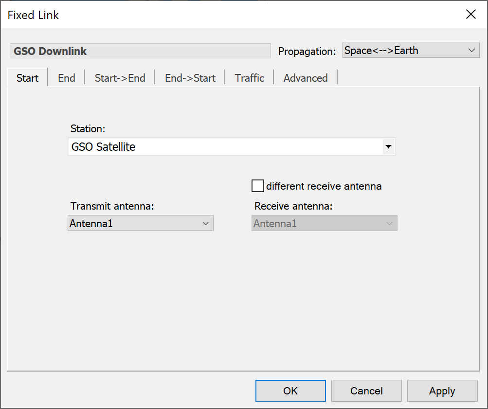
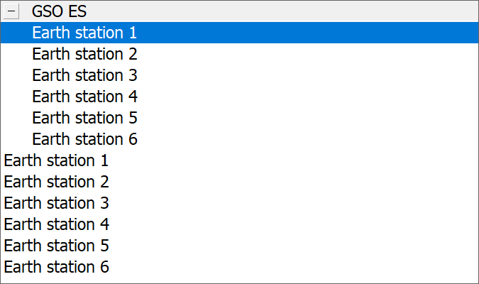
Select a Station to define the starting point of the Link from the drop-down list. If any Stations appear in Groups, the Groups will be shown, and you can expand each Group to show the Stations it contains.
If the selected Station has multiple Antennas or Beams, you will need to select from these as well.
The end station tab is the same as the start station tab except for the antenna and beam labelling.
Link Paths
Each Link can have two associated Link Paths. These are associated with two possible directions of communications for each Link, allowing you for example to model up links and down links without too much input data duplication. The Link Paths are called:
- Start to End – in the direction start station to end station
- End to Start – in the direction end station to start station
The StartEnd tab is shown below.
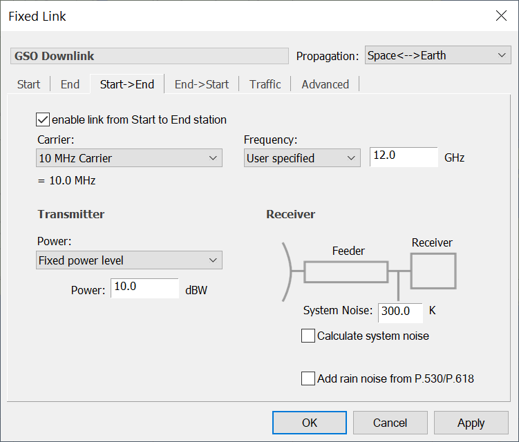
End to start and start to end tabs work in exactly the same way.
You can specify whether the link path is enabled or not using the check box at the top of the tab.
Frequency and Bandwidth of the Link
On each active Link Path you must select a Carrier (which defines the bandwidth) and a centre frequency.
Transmitter
For the start to end link path, this will be the start station. The main feature of the transmitter is its power. Power is made more compact by allowing you to say how you want to specify it before asking you for the relevant parameters. You can choose from the following options:
- Fixed power level: the power level is a fixed value
- Adaptive power control: the power level changes to achieve a target receive level
- PFD power control: the power level changes to achieve a target PFD
- Bandwidth control: the bandwidth changes rather than the transmit power
- Constant receive power : the receive level is fixed
- Random (specify limits) : power is random between some user defined limits
- Random (limits from antenna): power is random between the limits defined in the antenna
- Fixed amplification: the transmit power is the receive signal of the previous link plus a constant
- Table amplification: the transmit power is the receive signal of the previous link plus and an amplification factor that depends upon the receive signal
For the return direction (EndStart) there are two additional power options:
- Radar reflection
- Listen before transmit
More information on how to use these two options is given in the Technical Annex.
A detailed description of all the options is given in the Technical Note: Transmit Power Options
Tip: Note that the transmit power is referenced at the input to the antenna. See the Technical Annex for more information about link reference points.
Receiver
For the start to end link path, the end station is a receiver.
The main feature of the receiver is the specification of system noise. This is shown diagrammatically in the bottom right of the dialog.
If the calculate system noise option is selected, the software will compute the system noise from the temperatures and losses at the antenna and feeder you have already provided in the Antenna and Station dialogs. These contributions are shown on the diagram. The receiver noise figure must be provided to complete the calculation.
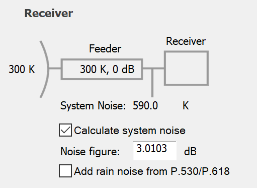
If the noise is not being calculated, the diagram is greyed out and a box is provided for the system noise figure.
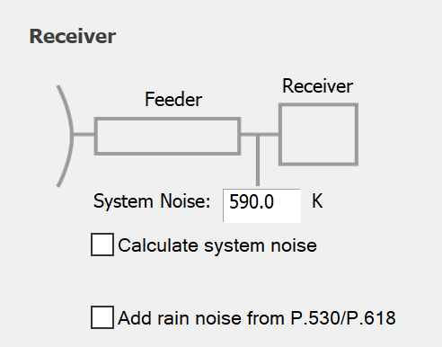
Note that the reference point is immediately after the antenna feed. The feeder loss is specified in the Station dialog (see Adding and Managing Antennas) for each Antenna. If you want to do your calculations at a reference point immediately after the antenna you should put zero in the for the feeder loss and specify the system noise directly.
If you have a rain model switched on (see Propagation Modelling) you can optionally include the increase in noise on a Link due to scattering by rain.
Advanced Options
The advanced tab allows you to override the propagation and statistics that are specified at simulation level. You can also set the link colour. This is shown below.
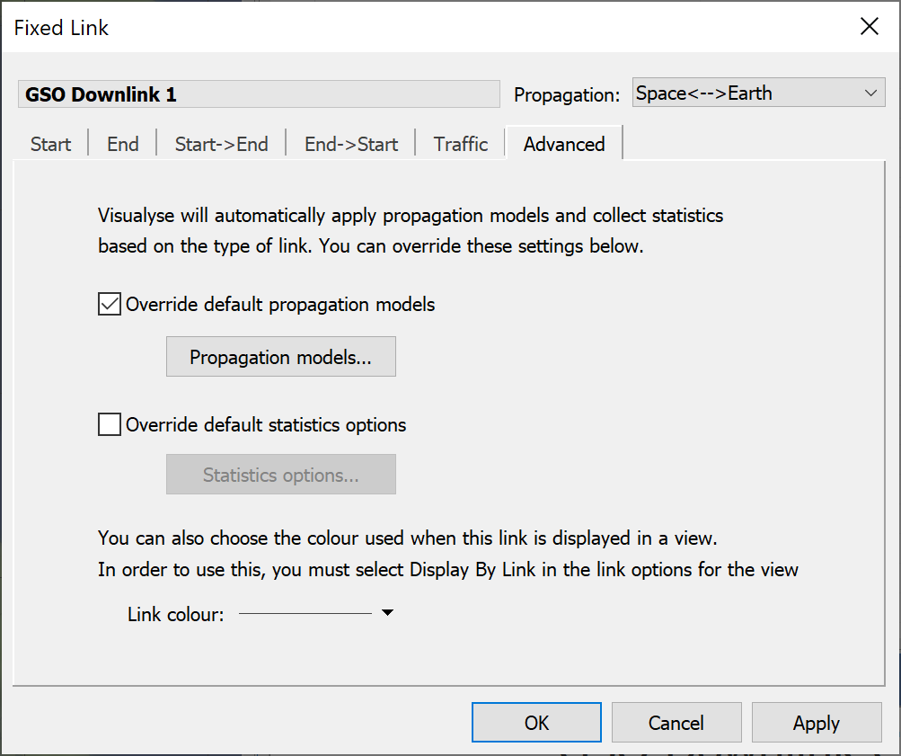
If you decide to override the default propagation models, click the Propagation models button. This will display the propagation options dialog.
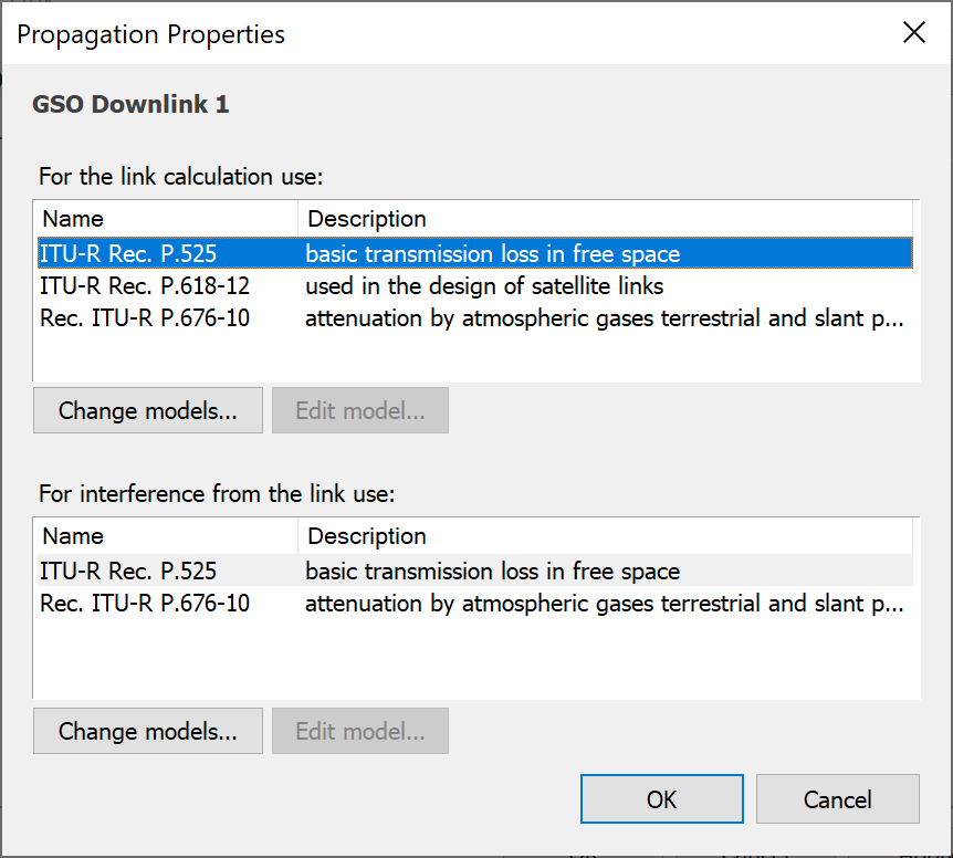
The default models for the link type will be displayed. Click “Change Models” to change the models that are used for this link. Double-click on a model or select it and click “Edit Parameters” to change the default parameters used for that model.
The statistics options work in the same way.
Traffic
As with Stations, the Traffic tab will not be shown unless the traffic module is enabled. If traffic is enabled, an extra tab called Traffic will appear.
You can decide whether to enable traffic modelling on the link and if so what traffic model to use. The Traffic modelling option is explained in the Module User Guide.