Frequency View
The frequency view can be used to show graphically the spectrum mask of transmitters and the receive filter characteristics, together with the frequency offset between them.
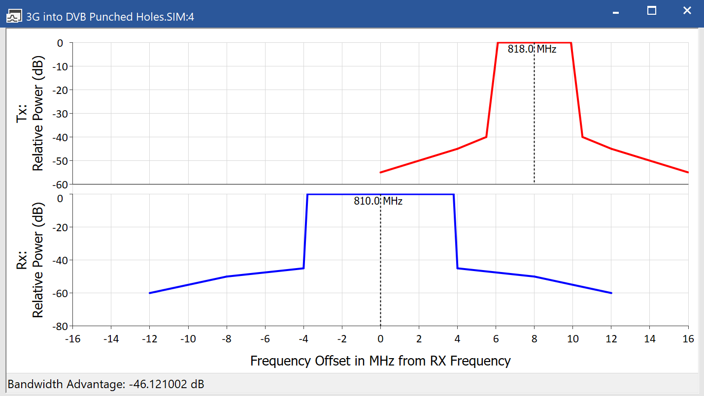
An example is shown in the figure below, taken from the “Digital Dividend” example file “3G into DVB Punched Holes.sim”.

The frequency view shows in the top half the transmit mask in terms of relative power in dB against frequency offset from carrier centre frequency. In the bottom half, using the same frequency scale, is the attenuation of the receiver in dB – again with respect to frequency offset from carrier centre frequency.
The two frequency scales are aligned to show to scale the relative frequency offset of the two links. In addition the central frequencies of the two links are displayed above each mask.
You can open a new frequency view by selecting menu option “Window | New | Frequency view” or clicking on the icon ![]()
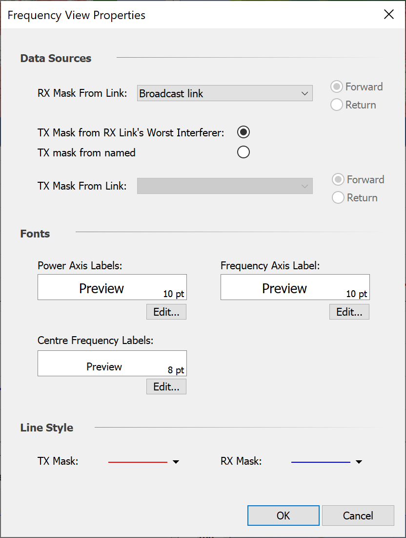
Having done that you can configure it by right clicking within the view to open the following dialog:

The first step to configure the view is to select the receiver of interest: the RX mask shown will use taken from the carrier for this link. The frequency axis of the view will have its zero frequency offset defined by this link’s centre frequency.
Then the transmit mask can be defined by one of two ways:
- From the carrier of the worst single interfering link into the selected victim link
- From the carrier of a specific link
In both the RX mask and TX mask cases if the link is bi-directional it will be necessary to select the direction as there could be different carriers and / or different frequency offsets between forward / return directions.
If the TX mask is taken from the RX link’s worst interferer, and the interference path has the “Bandwidth adjustment” option set to “Integrate masks” then the calculated Bandwidth Advantage will be shown in the view’s bottom left corner.
The view can be copied into the clipboard for pasting into other applications by clicking on the copy icon or selecting menu option “Edit | Copy”.
Note that this view updates during the simulation, so that if a frequency hopping system is used it will show the frequency offsets for the current time step – see the “Short Range” example file “WiFi and BT.SIM”