VisTools User Guide and Technical Annex
Documentation Control
| Date: | Software Version: |
|---|---|
| March 2022 | 7.10.4.0 |
Contact Information
You can contact us at:
Address Transfinite Systems Ltd, Suite 24 (5th Floor), AMP House, Dingwall Road, Croydon, CR0 2LX U.K
Phone +44 20 3904 3220
Fax +44 20 3904 3211
Email info@transfinite.com
Web www.transfinite.com
Transfinite Systems reserves the right to change features and screen layouts without notice.
©Transfinite Systems Ltd
Introduction
This document describes the calculations in the Visualyse Professional stand-alone engineering tool kit, VisTools. This application runs on a Windows PC and has interface as shown in the figure below:
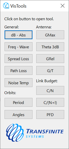
Each of the button activates a different dialog as described in the following sections.
Decibel to/from Absolute
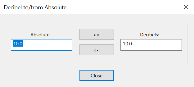
The dB tool converts between dB (d) and absolute (a) using:
Frequency to/from Wavelength
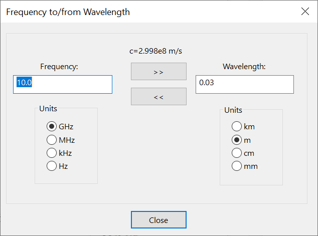
The Frequency tool converts between frequency and wavelength using:
where is the speed of light .
Calculate Spreading Loss
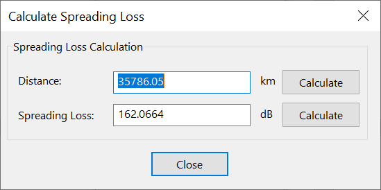
The spreading loss tool calculates the spreading loss used to calculate PFD. The parameters used are:
The spreading loss tool calculates the spreading loss used to calculate PFD. The parameters used are:
-
path length
-
spreading loss
Each of these three can be calculated from the other using:
Note that the distance is given in but the spreading loss is per .
Calculate Path Loss
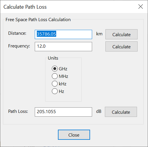
The path loss tool calculates the free space path loss. The parameters used are:
-
frequency and Frequency units
-
distance or path length
-
Path Loss
Each of these three can be calculated from the other using:
Noise Temperature Calculation
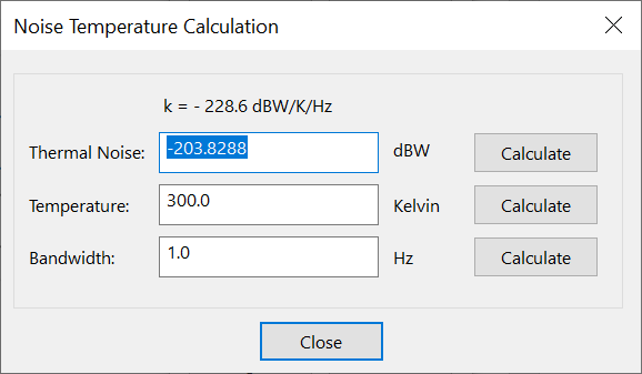
The noise tool converts between temperature in Kelvin to noise in . The following parameters are used:
-
temperature Kelvin
-
noise in in bandwidth
-
bandwidth in
These parameters are related using the following equations:
where is Boltzmann's constant in .
Orbit Period Tool
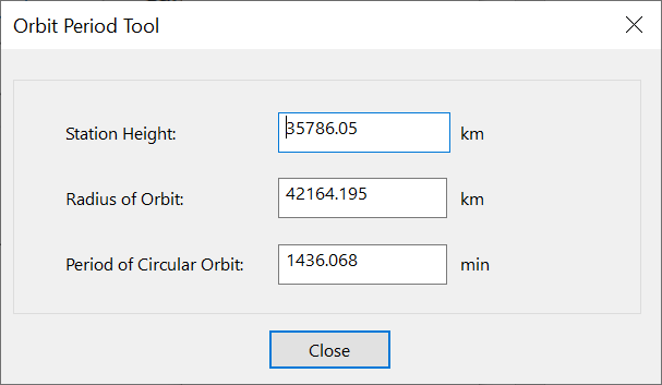
The orbit period tool can covert between orbit height and radius and calculate the associated period. The parameters are:
-
height of satellite
-
radius of orbit
-
period of circular orbit (minutes)
The equations are:
Where .
Then the period in seconds can be calculated using:
Where .
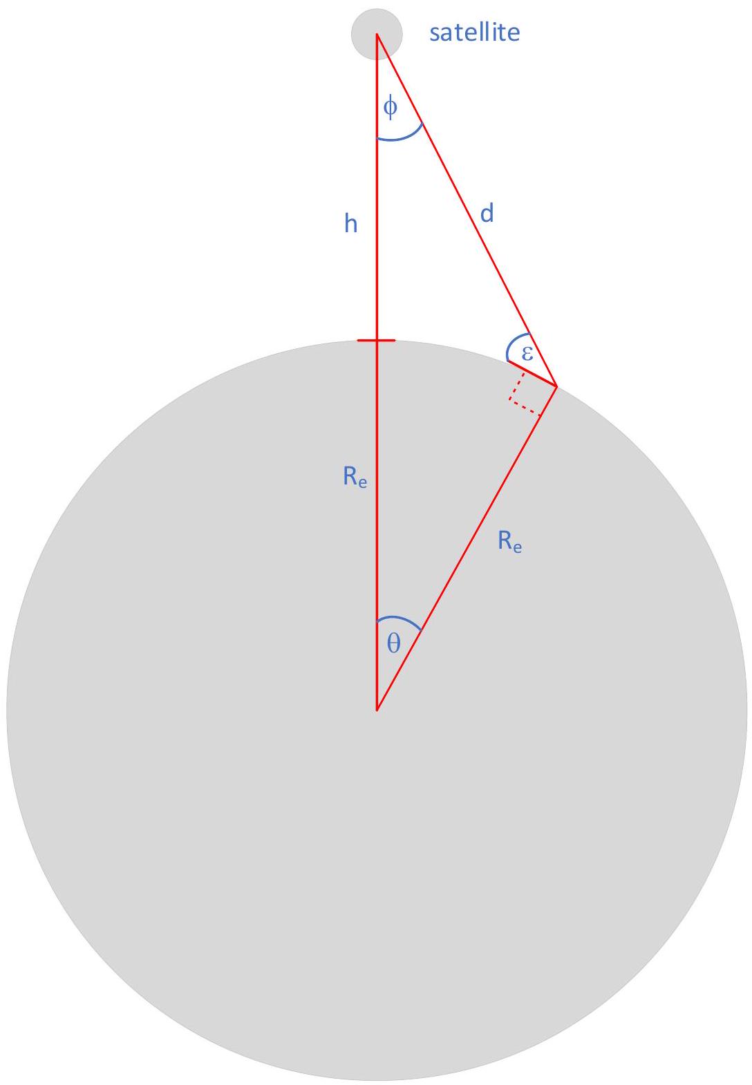
Orbit Field of View Tool
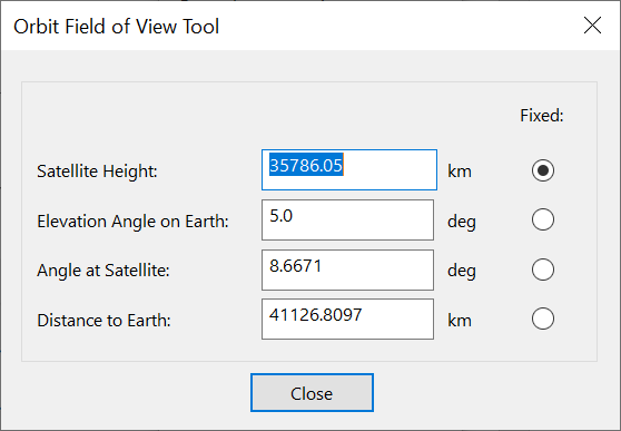
The angles tool provides information about satellite angles and distances. The parameters are:
-
height of satellite
-
elevation angle on the ground (deg)
-
half angle at satellite (degrees)
-
distance to Earth
These parameters are shown in the figure below:
The equations are:
Calculate Peak Gain
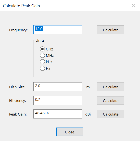
This tool calculates peak gain based on the following parameters:
-
frequency and frequency units
-
dish size
-
efficiency
-
peak gain
These parameters are related using the following equation:
Calculate Half Power Beamwidth
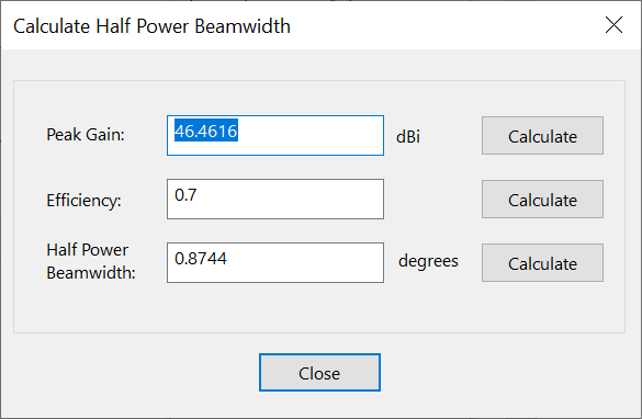
The half power beamwidth tool calculates half power beamwidth based upon the following parameters:
-
peak gain
-
efficiency
-
half power beamwidth,
These parameters are related using the following equation:
Calculate Relative Gain
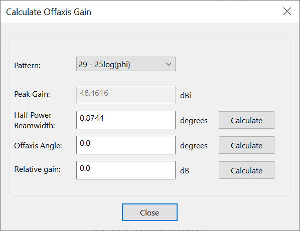
The relative gain tool calculates offaxis gain based upon the following parameters:
-
gaiin relative to peak
-
half power beamwidth (deg)
-
offaxis angle (deg)
Three gain patterns are available:
-
Pure parabolic
-
Side lobe with 29-25log
-
Side lobe with 32-25log
The sidelobe equations also use the peak gain calculated using the half power beamwidth tool.
These parameters are related using the following equations:
Parabolic:
Sidelobes:
Then:
When the gain pattern is parabolic, the first equation is used. When the sidelobes are used then the gain pattern follows the parabolic equation until it reaches the sidelobe, then continues until the gain .
Calculate G/T
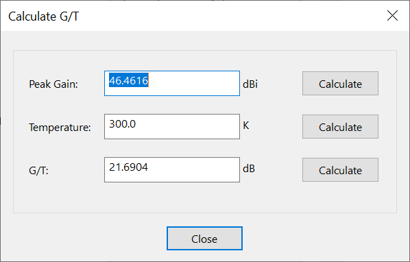
The tool converts between peak gain and temperature in Kelvin to . The following parameters are used:
-
peak gain
-
temperature in Kelvin (K)
-
ratio of gain to temperature in
These parameters are related using the following equations:
C/N Link Budget
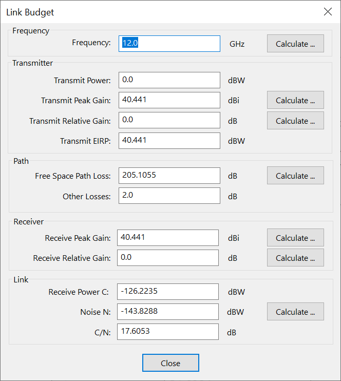
These various tools are combined to produce a link budget tool with the following parameters:
-
frequency, entered either directly or using the frequency tool
-
transmit power, entered directly, or calculated from transmit EIRP
-
transmit peak gain, entered either directly or using the peak gain tool
-
transmit relative gain, entered either directly or using the offaxis gain tool
-
transmit EIRP, either entered directly or calculated from or using:
-
free space path loss, either entered directly or using the path loss tool
-
other losses, entered directly
-
receive peak gain entered either directly or using the peak gain tool
-
receive relative gain, entered either directly or using the offaxis gain tool
-
receive power, either entered directly or calculated from EIRP or or using
-
receive noise, either entered directly or using the noise tool. Note that the noise tool includes the bandwidth
-
Receive , either entered directly or calculated using:
Note that:
-
If is changed directly the and transmit power fields update accordingly
-
If the EIRP field is changed directly, the , and transmit power fields update accordingly
-
If the transmit power field is changed directly, the EIRP, and , fields update accordingly
-
If the field is changed directly the , and transmit fields update accordingly
C/(N+I) Tool
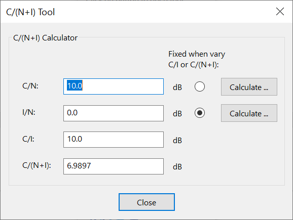
These tools can be used to calculate the link metrics , and . In this tool the:
-
"Calculate" button goes to the Link Budget tool which can be used to calculate the
-
"Calculate" button goes to the Link budget tool which can be used to calculate the
When the or are changed, this could be due to changes in the or I and an option allows the user to select which is fixed.
PFD / EPFD Tool
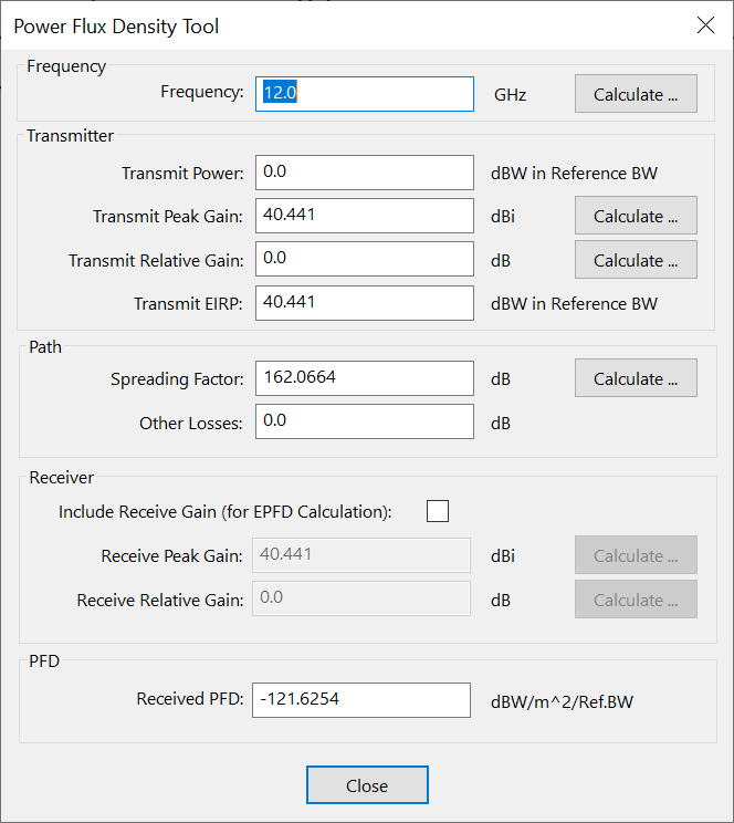
These various tools are combined to produce a PFD and EPFD tool with the following parameters:
-
frequency, entered either directly or using the frequency tool
-
transmit power, entered directly, or calculated from transmit EIRP
-
transmit peak gain, entered either directly or using the peak gain tool
-
transmit relative gain, entered either directly or using the offaxis gain tool
-
transmit EIRP, either entered directly or calculated from or using:
-
spreading loss, either entered directly or using the spreading loss tool
-
other losses, entered directly
-
receive peak gain entered either directly or using the peak gain tool
-
receive relative gain, entered either directly or using the offaxis gain tool
-
receive power flux density calculated from EIRP using
-
receive noise, either entered directly or using the noise tool. Note that the noise tool includes the bandwidth
-
Receive C/N, either entered directly or calculated using:
If the receive gain is included for EPFD calculations then:
- receive power flux density calculated from EIRP using
Note that:
-
If PFD or EPFD is changed directly the EIRP and transmit power fields update accordingly
-
If the EIRP field is changed directly, the PFD/EPFD and transmit power fields update accordingly
-
If the transmit power field is changed directly, the EIRP and fields update accordingly