Advanced Beam Options
For all Beams
For most purposes, you will only need to specify the gain pattern for a beam. However, in some circumstances you may need to specify default EIRP, frequency, noise and polarisation – this will depend on choices made in defining your Links and in most modelling situations, these parameters are specified directly in the Link and the Antenna parameters are ignored.
Example applications of Antenna Advanced parameters are for:
- Frequency re-use in multiple beam antennas
- To plot antenna footprints where no Link has been defined and a default frequency is needed
- To model simple variation in EIRP, as a random variable between a maximum and minimum value.
For traffic modelling you may need to define a maximum load parameter (see the Modules User Guide).
These parameters can be entered by clicking the ‘Advanced’ button.
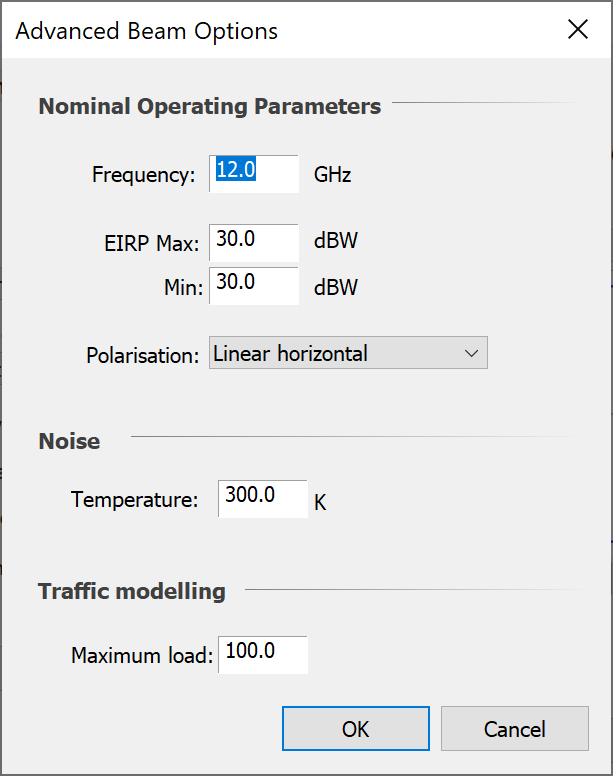
The noise represents the temperature of the Antenna (sky noise, plus earth noise etc) and can be used in the Link as part of the calculation of system noise. It will only be used if you decide not to enter the system temperature directly into the Link. If you specify this parameter and intend to use it, you must also enter the feeder loss (in the Station dialog) and the receiver noise figure (in the Link).
If you intend to specify the system noise temperature for your Link, then you don’t need to bother with Antenna temperature.
Note that the traffic modelling options will not be displayed unless the traffic module is enabled.
Shaped Beams
For shaped beams, there is another set of advanced options.
These allow you to add additional gain tables depending on the angle from the sub-satellite point. This allows you to model adaptive Antennas (sticky beams) using data derived from detailed models of the Antenna.
The options appear below the options described above.
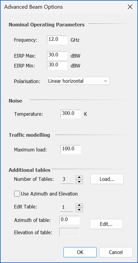
Set the number of tables using the spin control or click the “Load…” button to load the data from a TXT file (note: the format of this file is described in the Technical Annex).
To edit a table, select the table number using the spin control then type the Azimuth from the sub-satellite point in the box provided then click “Edit” to configure the table.
If the option “Use Azimuth and Elevation” is selected, then an Elevation value can be input for the table.
If the option "Latitude" is selected, then a Latitude value for the table can be input.
There are also options "Probability fixed" and "Probability random" which allow probabilities to be input for the table.
Contour Beams
There are additional parameters for contour beams which are shown under ‘Interpolation Options’.
The software calculates the gain from contours beams by interpolation. You can change the way in which the interpolation is performed by clicking the Advanced button.
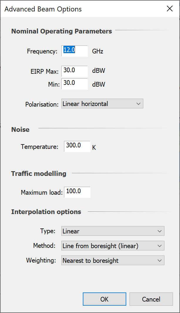
You can change the calculation method and the way in which multiple boresights are weighted in this process.
IMT-Model Non-Co-Frequency Parameters
There are additional parameters under the advanced beam options dialog when using one of the IMT-Models gain patterns. These allow the gain pattern to be different between co-frequency and non-co-frequency scenarios.
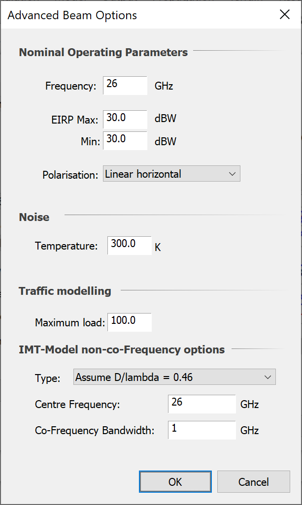
The following options are available:
- Use co-frequency pattern: the M.2101 pattern is used with D/lambda = 0.5 for both co-frequency and non-co-frequency scenarios
- Single element pattern: the M.2101 single element pattern is used if the victim centre frequency is non-co-frequency
- Assume D/lambda = 0.46: in the M.2101 gain pattern a D/lambda of 0.46 is used rather than 0.5
- Variable D/lambda: it is assumed that at the centre frequency supplied the D/lambda = 0.5, and so for other frequencies the D is derived and fixed but the lambda varies depending upon the victim frequency
The definition of what constitutes “co-frequency” and what “non-co-frequency” for the IMT-MODEL gain pattern is set via:
- Centre Frequency: this is the centre frequency that the IMT-MODEL antenna has been tuned to
- Co-Frequency Bandwidth: this is the total bandwidth that is defined as being co-frequency in range:
- Minimum = CentreFrequency – CoFrequencyBandwidth./2
- Maximum = CentreFrequency + CoFrequencyBandwidth./2
Outside this frequency range the interference path is assumed to be non-co-frequency.
Note that to activate these non-co-frequency gain patterns it is necessary to configure the Interference Path as described in Interference Paths.