Circular and Elliptical Beams
For circular and elliptical beams, the gain pattern is defined by the roll-off mask and a few Antenna parameters.
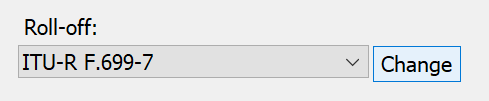
Roll-Off
To change the way the roll-off is defined, choose the Change button next to the roll-off field.
The Roll-off dialog is shown below.
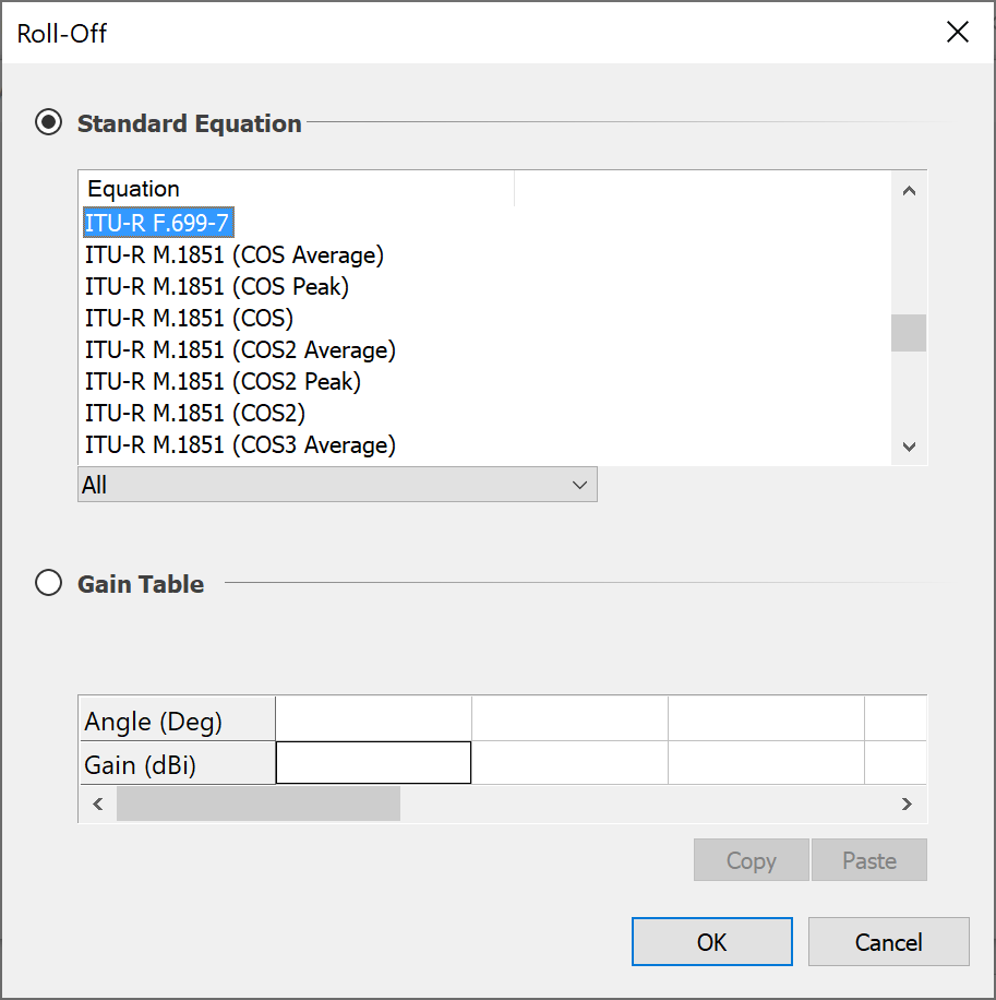
The dialog provides two options. You can use either:
- a standard equation as a mask, or
- a table of gain/off-axis angle pairs
Roll-Off Masks
Visualyse already includes 80 or so standard roll-off masks. These are described in detail in the Technical Annex
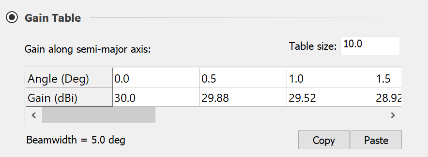
Gain Tables
The gain table option allows you to enter the complete roll-off as a set of gain, angle pairs. To help with data entry, you can now copy and paste data to and from different sources, including from Excel spreadsheets.
In this case is no need for you to supply other Antenna parameters such as peak gain and beamwidth. This will be indicated as in the dialog – under Antenna parameters it will say ‘determined by the gain table’.
If the beam shape is elliptical, text will appear above the gain table to indicate that the gain along the semi-major axis is required. In both the circular and elliptical cases, the beam width (as derived from the table) is displayed.
Antenna Parameters
There are four parameters that are commonly used in defining Antenna characteristics. The four are related in standard Antenna theory and no more than two are ever needed to fully define an Antenna.
As an engineer you may know your Antenna diameter but not its beamwidth, or vice-versa. Alternatively, you could be working to a standard antenna and know only the D/
The ‘Antenna parameters drop-down allows you to say which characteristics of the Antenna you know.
Depending on the option selected, a number of applicable fields will appear. You can then fill in these fields with the appropriate information.
For circular beams the combinations are as follows:
- Dish Size & Efficiency
- Full Beamwidth & Peak Gain
- Footprint Diameter
For elliptical beams the antenna must be defined by peak gain and the two beamwidths.
For the case when a gain table defines an elliptical beam, the semimajor axis is determined from the data you have already put into the table (or the default data) and therefore does not need to be entered here. You must however, give the minor axis, and Visualyse will then scale the roll-off in all directions other than along the major axis to give the correct ellipticity.
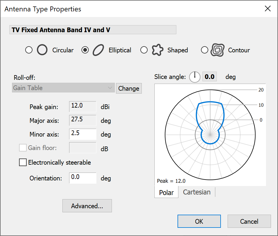
Beam Roll-off Preview
A preview of the roll-off is shown to the right of the Antenna parameters. You can choose between polar or Cartesian plots. Each plot has its own controls that allow you to modify the display.
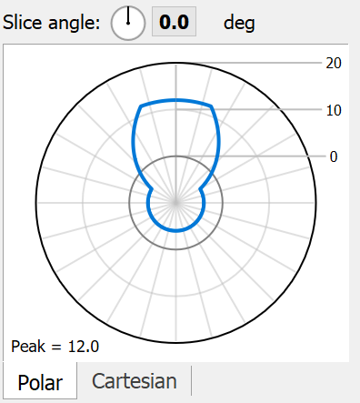
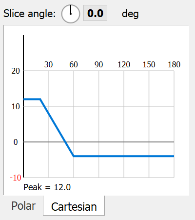
For both plots, you can change the slice angle by clicking and dragging the angle control. On the Cartesian plot, you can also zoom into areas of the graph.
In order to understand the meaning of slice angle – if you consider and elliptical beam, the slice angle of the major axis is 0 or 180. The minor axis is 90 or -90.
These plots are provided to give you a basic idea of the shape of your Antenna while you are editing it. Additional plotting options are provided on the Antenna list dialog