Contour Beams
Visualyse allows you to create, import and edit antennas that are defined in terms of their gain contours in GIMS format.
You can create and edit beams as polygons using the mouse to click on a map view. This allows you to define coverages from scratch or to approximate coverages that you only have as printed map.
Visualyse provides facilities to import data directly from the ITU database and also to enter contours as polygons using the mouse.
Visualyse then converts these to a grid of gain vs. Antenna angles and stores both the contours and the grid using a proprietary algorithm. In order to do this conversion, Visualyse needs a reference satellite longitude. This is the longitude of the satellite from which the contours were plotted or the longitude at which they will be used. If you subsequently change the longitude of the satellite using the Antenna, the Antenna coverage will move with the satellite.
A new feature is that for patterns imported from GIMS, you can now select the GIMS algorithm for the interpolation of the gain to points in between contours – which ensures compatibility with results obtained using ITU-R software. This option is set in Visualyse Settings (see Visualyse Default Parameters).
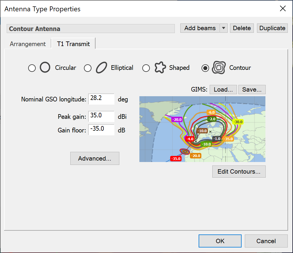
The dialog is shown below.
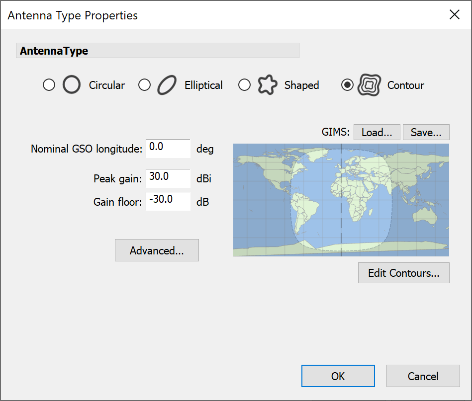
Before you can enter any contours, you need to specify the longitude of the GSO satellite that would host the Antenna.
Next you need to enter the limits on the gain: the peak gain and the gain floor (the limit of relative gain for points along way from the peak gain point). Once you have done this, you can go straight in and add some contours. Click Edit Contours. The Edit Contours dialog will appear.
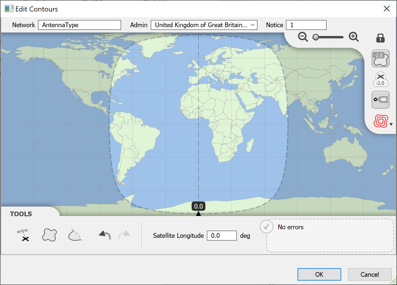
Setting Network Details
Use the controls at the top to set the name, admin and notice id for the network that the beam is to be a part of.

The orbital position of the satellite is set from the toolbar at the bottom of the window. When you change this, you’ll see that the highlighted area of map representing the satellite field of view will change accordingly.
Adding Boresights
Click the Add Boresight button
 , then click on the map to add a boresight (hold SHIFT while clicking to add more than one).
Editing Boresights
You can move a boresight by clicking on it, holding the mouse button and dragging it to a new location.
To edit a boresight, first click to select it. You’ll see a small toolbar appear below the selection rectangle. This is called the Selection Toolbar.
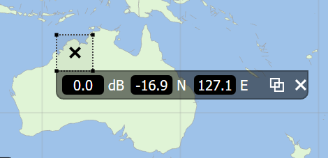
From here you can set the relative gain and the exact location in latitude and longitude coordinates. A boresight can also be duplicated and deleted from the selection toolbar.
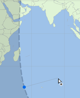
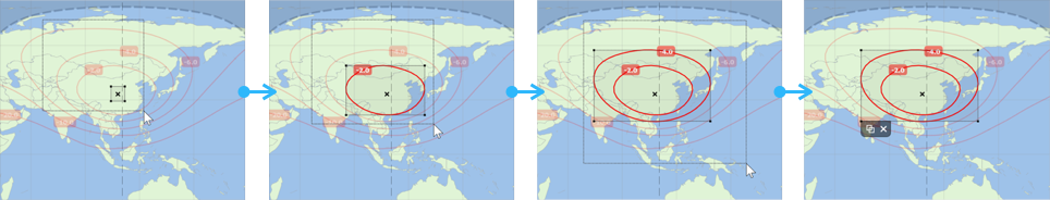
Adding Contours
To add a Closed Contour, click on the Closed Contour button:

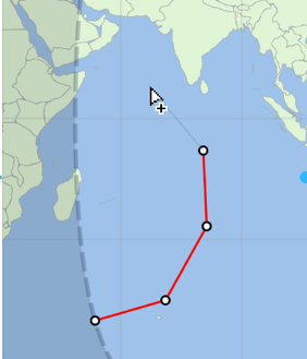
- Click to add the first point then continue clicking to add more points. You can also hold the mouse button and drag to draw.
- To complete the contour, click on the first point again or you can double-click to add the last point and finish, or press ENTER.
- The completed contour is shown as the current selection. Note that you can cancel at any time by pressing ESC.
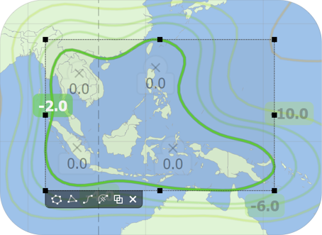
- You then need to set the relative gain for the contour. This is shown in the label on the contour itself. By default, it’s set to zero. To change it simply click on it then type in the relative gain you want and either click away or press ENTER.
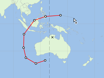
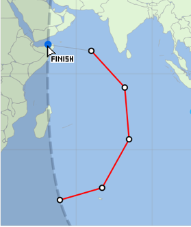
To add an Open Contour, click on the Open Contour button:

- Open contours must start on the field of view. When you move the mouse, you’ll see where the first point will be. When you click, both the first point and the clicked point will be added.
- Keep clicking to add more points. You can also hold the mouse button and drag to draw.
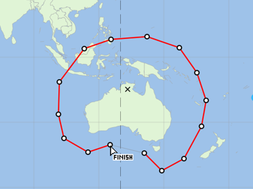
- Open contours must end on the field of view. When you get close the software will detect this. Simply click to finish. You can also double-click on the last point you want to add, or press ENTER, and the end point will be added automatically.
- The completed contour is shown as the current selection. Note that you can cancel at any time by pressing ESC.
Editing Contours
Click on a contour to select it. Just like boresights, contours have their own selection toolbar. Buttons are provided to Edit Points, Reduce Points, Smooth Points, Switch to Open Contour, Duplicate and Delete.

Editing contour points is described in the next section.
Reducing the number of points will intelligently reduce the number of points by around half. Smoothing on the other hand will re-sample the contour and add extra points to smooth out any sharp edges.
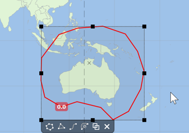
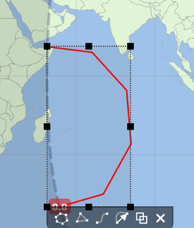
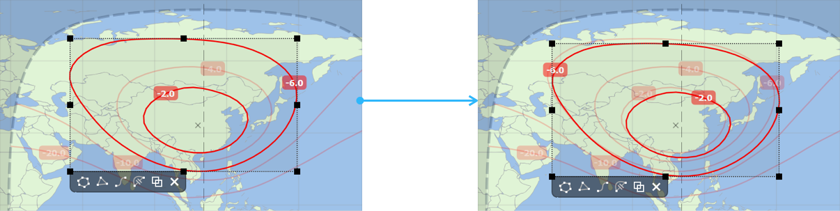
You can resize a contour by dragging one of the eight control points that surround the selection rectangle.
Editing Contour Points
To edit a Contour (be it Closed or Open), either double-click on it or select it and then press the Edit Points button on the Selection Toolbar or press ENTER.
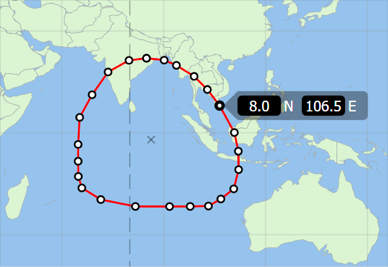
Click on a point to select it. Hold SHIFT to select multiple points it and then press the Edit Points button on the Selection Toolbar or press ENTER.
Click on the latitude or longitude boxes to make precise positional changes for the selected point
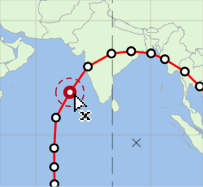
Hold CTRL while hovering on a point then click to delete it. You can also delete any selected points by pressing the DELETE key
Hover near a segment and click to insert a point
You can click on a point and drag it to a new position. You can also use the cursor keys to move the selected point by small amounts up, down, left or right. Hold SHIFT while doing this to move the point by a larger amount each time. The same applies to selections containing multiple points.
Pressing the TAB key will select the next point in the contour and SHIFT + TAB will select the previous point.
To finish editing either click on the Map or another item or alternatively press ESC.
Detaching from the Field of View
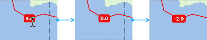
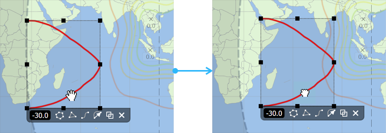
As mentioned earlier, open contours should start and end on the satellite field of view. If you drag an open contour, then the end points will always remain on the field of view.
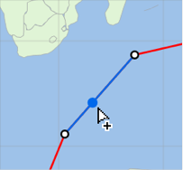
If you want to detach the end points from the field of view, there are a couple of ways to do this. If you want to move the whole contour, then simply click and drag it but hold SHIFT as you do this. The end points will then detach.
To re-attach the end points do exactly the same thing. Once an end point gets close to the Field of View both end points will re-attach at the nearest intersection.
If you only want to move the end points then first edit the contour. Click and drag an end point while holding SHIFT. The point will switch between being unattached or detached. Note that reattaching will only happen when you drag close to the field of view.
Warnings and Errors
You may notice that as you start to construct your shaped beam an orange panel will appear in the bottom-right corner of the application window. This shows any warnings or errors. These are mostly advisory so that you can check your beam will conform to GIMS requirements as you go along.
If there are no errors or warnings, you’ll see this:
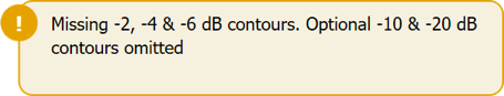
If there are any warnings or errors, you’ll see something like this:
Multiple Selections
You can select multiple contours and boresights and then move, duplicate or delete all of them in one go. There are two ways to do this. You can click on an empty area of the map and then drag out a selection rectangle. Any contours or boresights that are caught in the rectangle will be selected. Alternatively just hold SHIFT and click to add or remove items from the selection.
Multiple selections have their own Selection Toolbar. If you have a combination of boresights and contours then you will only get options to Duplicate or Delete.
However, if your selection only contains contours then you’ll get all the options that are available to you when just a single contour is selected. This allows you make changes like smoothing or point reduction to several contours at once. You can also resize the selection when it only contains contours. All contours will size proportionally and maintain the same relative spacing from each another.
Copy and Paste
You can copy any selected contour or boresight, or any selected combination by using the standard keyboard shortcut CTRL+C. To paste the copied selection use the standard keyboard shortcut for paste, CTRL+V.
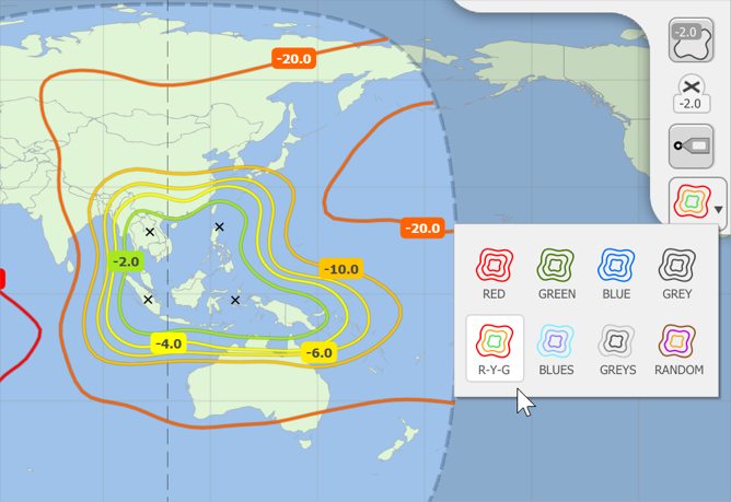
Display Options
There are several options for controlling the way that items are displayed. Click the Contour Colours button to choose one of eight built in colour schemes for displaying contours. Click on the map to finish.
When you are finished, click OK to return to the Antenna dialog.
You will now see your contours displayed in the preview window.
If you have the contour data in GIMS format, you can load this into the software by clicking the Load button. Contours can also be saved to this format.