Propagation Modelling
Propagation modelling in Visualyse is dealt with at simulation level. This means you define a global propagation environment in terms of which loss models to apply to different types of Link, and Visualyse does the rest. The global environment can be over-ridden for each link individually.
Visualyse classifies Links into the following types:
- Terrestrial fixed
- Terrestrial mobile
- Space earth
- Space – space
- Broadcasting
- User defined (as many additional ones as you need)
For each Link type you define a set of propagation models to be applied. Different models to can be applied depending on whether the Link is victim or interferer.
We refer to the whole set of propagation models for the different Link types as the Propagation Environment.
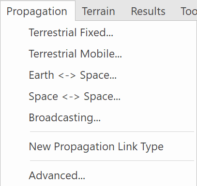
In order the set your propagation environment begin with the Propagation menu (shown below).
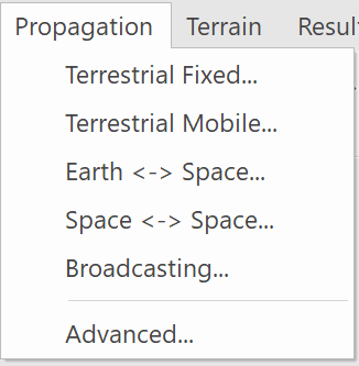
To change the models used by a particular Link type, simply select the Link type from the Propagation menu. The properties dialog for the selection will be displayed.
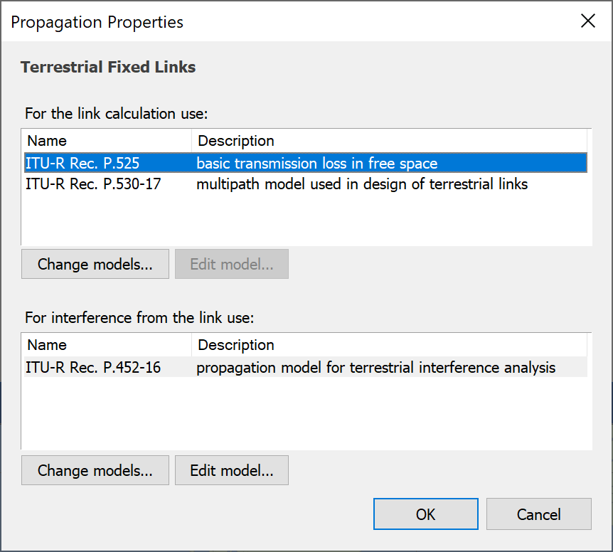
The dialog above shows the models that will be used for terrestrial fixed Links.
You may wish to treat propagation in a different way when considering wanted and interfering signal levels – this is normal practise if you are following ITU-R Recommendations. In Visualyse, a Link can be used as both a victim and interferer.
You can change the models used by clicking the appropriate ‘Change Models’ button. The Propagation models dialog will appear.
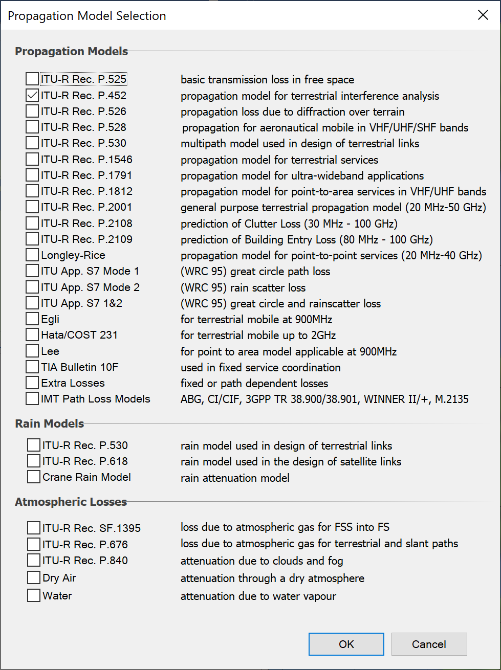
You can select any combination of the base propagation models plus any rain or atmospheric models. Visualyse does not restrict the combinations you choose but will generate a warning message (which you can ignore) if you choose two models, each of which has a free space element included in it. This helps prevent double counting of free space loss.
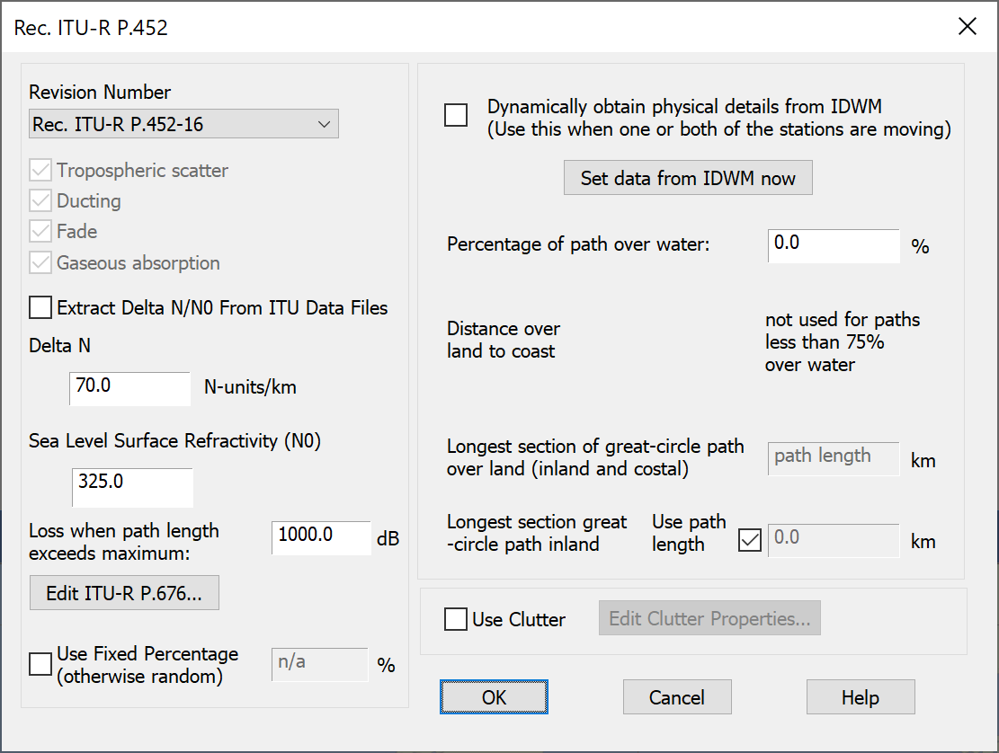
Propagation Model Parameters
Many of the propagation models have associated parameters. You can edit these by double clicking on the model or by selecting it and clicking the Model Parameters button. This will show the propagation parameter dialog for the model. An example is shown below.
A description of the available propagation models is given in the Technical Annex.
Creating Your Own Propagation Link Types
You can create your own propagation Link types – an example application might be if you are modelling a mobile system with go and return links on widely different frequencies. In this case you may want to have ‘UHF Mobile’ and ‘VHF Mobile’ modelled as different Link Types.
To do this, select Advanced from the Propagation menu. The custom propagation Link types dialog will appear.
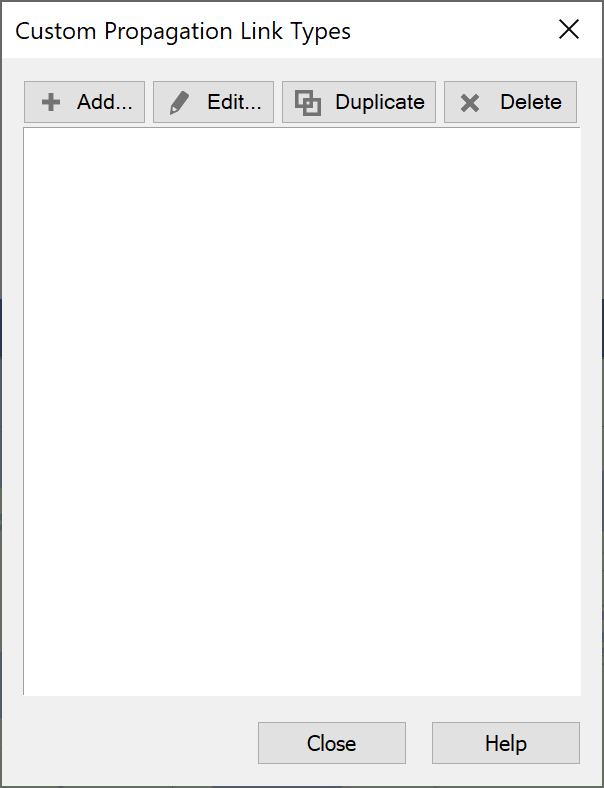
Click Add to add a new Propagation Link type. The edit dialog for the new Link type will appear. This is the same as the dialog for built in Link types, except that there is a field for the name at the top of the dialog.
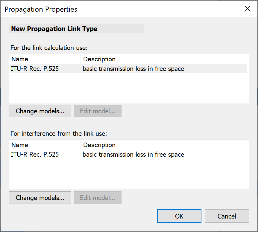
Make your changes and click ok. You will be returned to the previous dialog. Click Close and then click the Propagation menu again. You will see your new propagation Link type under the built in Link types.
The Technical Annex contains a tutorial on propagation which is a useful introduction for the non-specialist on the selection and use of propagation models for interference analysis.