Stations
Stations define the locations of your transmitters and receivers. They also define the dynamics i.e. how the scenario will evolve.
The Station object includes, by reference, one or more Antennas which the Station points using one of the eight pointing options.
Stations are an essential part of the definition of the geometry of a scenario. Later we will see how this geometry is completed and the topology defined by the addition of Link objects.
Creating Stations
The Station List can be accessed from the Model menu or from the toolbar. The list is shown below.
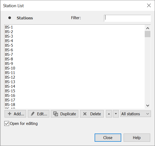
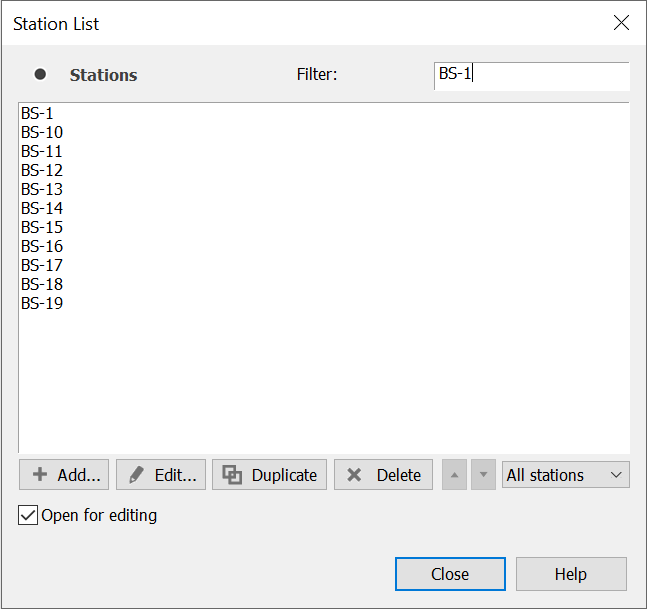
This list and its window can be filtered in two ways. First, it can be filtered on name.
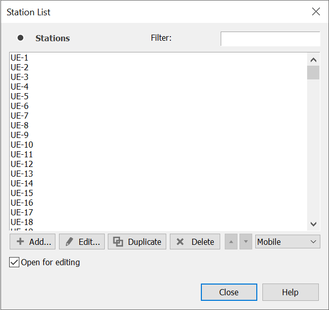
Secondly you can filter the list by Station type.
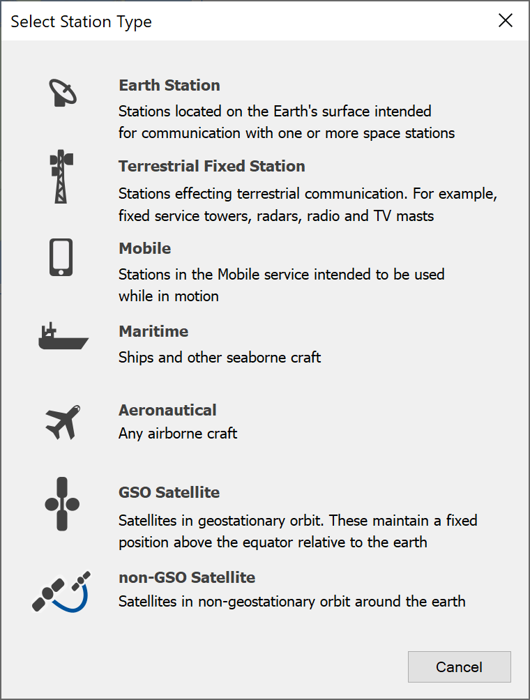
To add a Station from this location, click the add button. This will display a Station type selection dialog.
By default, the software opens a new edit dialog as soon as you create a Station. You can switch off this option by unchecking the box in the bottom right of the List Dialog
Station Types in Visualyse
Visualyse Professional has seven station types:
- Earth Station
- Terrestrial Fixed Station
- Mobile Station
- Maritime Station
- Aeronautical Station
- GSO Satellite
- Non-GSO Satellite
The difference between the various types relates to fundamental difference in their dynamics – e.g. terrestrial fixed stations are constrained to move with a fixed point on the earth’s surface, GSO satellite have a fixed longitude in the geostationary orbit etc.
Logically there is no distinction between an Earth Station (commonly taken to be a satellite earth station) and a terrestrial fixed station – in fact some investigation will show that the only difference between the dialogs is in the default icon that is used.
It is recommended that you read Stations, which give information relevant to all station types.
The other subsections below give information specific to the station type you may wish to model.
Antenna and Beam Pointing
Common to all Station types is a selection of the method used to point the antennas.
Antennas can point in one of eight ways:
- Fixed pointing direction
- Point at another Station
- Rotate in the azimuth plane
- Scan between two azimuths
- Allow the Link to set pointing
- Point at another Station OR the common volume
- Track a station with fixed elevation
- Point at another station using random offsets
- Elevation by latitude
In addition, electronically steerable beams can have their pointing angles changed by Links.
These options are described below.
Note that all Antennas have their own position and velocity vectors based upon the position and velocity vectors of the containing Station, with offset for Antenna height if required.
Fixed Pointing Direction
In this case the user specifies the (azimuth, elevation), and these values are fixed for the duration of the run for the relevant beam or Antenna.
Point at Another Station
Fixed on Station can take one of the following as it’s tracking target as:
- Fixed upon a target Station
- Fixed upon a target Antenna
In each case at each time step the pointing angles of the Antenna are set up using the vector position and velocity of this Antenna and the vector position and velocity of the target Station/Antenna.
Rotate in the Azimuth Plane
Scanning Antennas have the following parameters defined:
- Elevation angle
- Start azimuth
- Scan rate in degrees / second
Scan between two azimuths
Scanning Antennas have the following parameters defined:
- Elevation angle
- Start azimuth
- End azimuth
- Scan rate in degrees / second
Allow the Link to Set Pointing
These Antennas have their pointing angles updated by a Link during Link update if the Antenna is used, otherwise the angles are not changed.
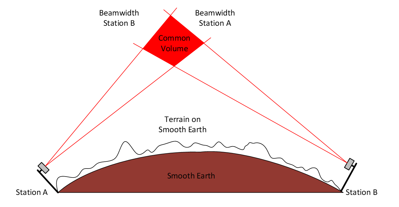
Point at Another Station or the Common Volume
In this case the Antenna will point in the direction (azimuth) of the selected Station, but that Station is (or becomes if the Station is moving) transhorizon, will point at the horizon in the direction. In effect this is how a troposcatter system points its Antennas.
The ‘common volume’ is indicated in the diagram below
Track a station with fixed elevation
This option is as “Point at Another Station” but the user can enter a fixed elevation value that is used at every time step instead of the calculated value.
Point at another station using random offsets
This option is as “Point at Another Station” but the user can enter a random offset range for azimuth and elevation that are used at every time step instead of the calculated value.
Elevation by latitude
A table of elevation angle vs. latitude should be entered together with the azimuth to use. At each time step the current latitude of the station will be used to derive an elevation angle from the table using linear interpolation. For non-GSO systems the coordinate reference system should be set to “North based”.
Note on Electronically Steerable Beams
If a beam is defined in the Antenna dialog as ‘Electronically Steerable’ the point angles can be defined by reference to a Link where the end point of a link moves, or is subject to handover, the point angles of the beam may change from whatever is defined in the Station.