Propagation models
Visualyse Professional contains a number of propagation models that can be activated either individually or in combination. These are described in the sections below.
- ITU-R Recommendations
- Other Standard Models
- Terrestrial Mobile
- Fixed loss Models
- Extra Clutter Models
- Other Models
- Use with Define Variable Module
ITU-R Recommendations
- Recommendation ITU-R P.452
- Recommendation ITU-R P.525
- Recommendation ITU-R P.526
- Recommendation ITU-R P.528
- Recommendation ITU-R P.530
- Recommendation ITU-R P.530 Multipath
- Recommendation ITU-R P.530 Rain Fade
- Recommendation ITU-R P.618
- Recommendation ITU-R P.676
- Recommendation ITU-R P.840
- Recommendation ITU-R SF.1395
- Recommendation ITU-R P.1546
- Recommendation ITU-R P.1791
- Recommendation ITU-R P.1812
- Recommendation ITU-R P.2001
Recommendation ITU-R P.452
Prediction procedure for the evaluation of microwave interference between stations on the surface of the Earth at frequencies above about 0.7 GHz
This option uses the model in Recommendation ITU-R P.452 for line of sight and trans-horizon loss valid for frequencies between 100 MHz and 50 GHz, though recent research suggests it might also be applicable at higher frequencies. Visualyse Professional includes all the key components of the model, including free space path loss, multi-path enhancements, gaseous absorption, diffraction, ducting and layer reflection/refraction, troposcatter and clutter loss.
Data needed for the model can be derived directly from the IDWM database if you are using the IDWM module, otherwise they must be input by hand. If a terrain database is available it will be used to derive parameters relating to the path including diffraction. The clutter model can use the land usage database or parameters entered by hand.
The associated percentage of time can either be user-entered or selected at random for Monte Carlo style analysis. The range in the Recommendation is 0.001 % to 50%, reflecting the fact that this model is designed for interference paths and so does not include effects for over 50% of time such as deep fades.
Recommendation ITU-R P.525
Calculation of free-space attenuation
This is the basic free space path loss that can be used for all paths at all frequencies. Note that by default for all paths including terrestrial no consideration is made as to whether there is line of sight, and losses increase steadily by distance.
Recommendation ITU-R P.526
Propagation by diffraction
Recommendation ITU-R P.526 defines models to be used in calculating diffraction losses for trans-horizon links for frequencies above about 30 MHz. Visualyse Professional implements both the smooth Earth model and the modified three-knife edge Deygout construction when terrain data is available.
Recommendation ITU-R P.528
Propagation curves for aeronautical mobile and radionavigation services using the VHF, UHF and SHF bands
This Recommendation is designed to predict propagation loss for air to ground / ground to air links. It gives curves of loss vs. distance for frequencies 125, 300, 1200, 5100, 9400 and 15 500 MHz and at TX/RX heights of 15m, 1 km, 10 km, and 20 km for probabilities of 5%, 50% and 95% of time. Interpolation is used to derive the loss for other frequencies, heights and percentages of time.
Recommendation ITU-R P.530
Propagation data and prediction methods required for the design of terrestrial line-of-sight systems
Visualyse Professional contains two of the propagation models in Recommendation ITU-R P.530 - rain and multipath fading, as describing below.
Parameters in various equations within the Recommendation have been derived from fading data from links operating in the range 450 MHz – 37 GHz, though they should be valid up to frequencies of 50 GHz.
Recommendation ITU-R P.530 Multipath
This option uses the fade distribution defined in Method 1 of Recommendation ITU-R P.530 to generate a fade or multipath enhancement either for a specific percentage of time or at random using a Monte-Carlo technique.
This method is applicable to lineofsight fixed links and is intended for initial planning and link design. The geoclimatic factor K parameter is derived from the Recommendation.
Recommendation ITU-R P.530 Rain Fade
This option uses the model defined in Recommendation ITU-R P.530 to generate a rain fade loss. It is intended to be used for line-of-sight fixed links.
The rain rate can either be entered directly or read automatically from Recommendation ITU-R P.837. The associated percentage of time can be either entered directly or generated at random for Monte Carlo analysis.
Recommendation ITU-R P.618
Propagation data and prediction methods required for the design of Earthspace telecommunication systems
This Recommendation models rain attenuation on earth to space / space to earth links and the rain rate can come from ITU-R Recommendation P.837 versions or directly entered by the user. It is valid for frequencies up to 55 GHz.
The associated percentage of time can be either entered directly or generated at random for Monte Carlo analysis.
Recommendation ITU-R P.676
Attenuation by atmospheric gases
This method implements losses due to dry air and water vapour defined in Annex 2 of Recommendation ITU-R P.676, and is intended to be used for earth to space / space to earth links. It is valid for frequencies from 1 GHz to 350 GHz.
The values of the temperature, water vapour density and pressure can be entered directly.
Recommendation ITU-R P.840
Attenuation due to clouds and fog
This method implements losses due to attenuation from cloud and fogs as described in Recommendation ITU-R P.840, and is intended for earth to space / space to earth links above about 10 GHz.
The values of the water concentration in the cloud and associated percentage of time can be entered directly.
Recommendation ITU-R SF.1395
Minimum propagation attenuation due to atmospheric gases for use in frequency sharing studies between the fixed-satellite service and the fixed service
This model calculates the attenuation due to atmospheric gases in more detail for low elevation paths than the direct method in Recommendation ITU-R P. 676. It fits a set of curves to a numerical integration at key frequencies.
Recommendation ITU-R P.1546
Method for point-to-area predictions for terrestrial services in the frequency range 30 MHz to 3 000 MHz
This propagation model is designed for use in modelling terrestrial services; in particular point-to-area predictions in the frequency range 30 MHz to 3 GHz.
Propagation parameters required by this model such as distance over water and whether warm water can be automatically extracted from IDWM or entered by hand.
The clutter model can use the land usage database or parameters entered by hand.
Note that this model calculates loss assuming high height transmitter and low height receiver and it is assumed that the loss in the return direction is then the same. The loss is calculated to a receiver height of 10m and then adjustments must be made for the actual receiver height.
Recommendation ITU-R P.1791
Propagation prediction methods for assessment of the impact of ultra-wideband devices
This model is a generic propagation model for short range scenarios built up work within the ITU-R studying ultra-wideband (UWB) devices. In the Recommendation it is basically a dual slope model with log-normal distribution: however we have included a number of extensions that were discussed during its development to make it a more generic short range propagation model.
In its more flexible generic form it comprises four elements:
- Basic loss: this can either be a single slope or dual slope, with a specified break distance and either one or two slopes. For wide band signals such as UWB it should use the adjusted basic path loss that takes account of the frequency range
- Optional indoor-outdoor propagation loss: it is assumed that the loss varies depending upon the building type and distance to exterior wall, with distribution defined by two break points and assuming loss is capped below and above and with linear interpolation between break points
- Optional additional log-normal loss with mean zero and standard deviation a user entered parameter, which can be different before and after the break point
- Optional additional loss, to cover other propagation effects
The log-normal loss can include enhancements, which could in theory result in less loss than would be the case with free space path loss. The loss can therefore be capped at this value to ensure physically plausible results.
Recommendation ITU-R P.1812
A path-specific propagation prediction method for point-to-area terrestrial services in the VHF and UHF bands
This propagation model is designed for use in modelling terrestrial services; in particular point-to-area predictions in the frequency range 30 MHz to 3 GHz.
Conceptually it is a mixture of Recommendations ITU-R P.452 and ITU-R P.1546 using:
- The path profile extraction and analysis method in ITU-R P.452 to work out propagation loss taking into account details of the terrain
- The clutter loss and percentage of locations within a pixel methodology within ITU-R P.1546.
The propagation model in ITU-R P.452 can calculate propagation loss for percentages of time down to 0.001% for frequency over about 700 MHz. However it is not feasible at present to predict propagation losses for very small percentages of time for the lower frequencies ranges covered by ITU-R P.1812: hence it is restricted to percentages between 1 and 50%.
Visualyse Professional includes all the key components of the model, including gaseous absorption, fading, ducting, troposcatter and clutter. Data needed for the troposcatter model can be derived directly from the IDWM database if you are using the IDWM module, otherwise they must be input by hand. If a terrain database is available it will be used to derive parameters relating to the path including diffraction. If a land use database is available it will be used to adjust the path profile with the heights indicated for each clutter category.
Propagation parameters required by this model such as distance over water and whether warm water can be automatically extracted from IDWM or entered by hand.
Recommendation ITU-R P.2001
A general purpose wide-range terrestrial propagation model in the frequency range 30 MHz to 50 GHz
This propagation model is designed for terrestrial sharing scenarios, in particular for use in Monte Carlo style methodologies.
Many of the other propagation models handle fading and enhancements separately. For example in sharing scenarios involving the fixed service there are two models:
- Wanted path: as well as free space path loss, Rec. P.530 is used to model fades on the link below the 50% of time level
- Interference path: Rec. P.452 is used to model interference including enhancements above the 50% of time level
When undertaking Monte Carlo modelling it is important to model the full range of probabilities for wanted and interfering paths so that the convolution of C/(N+I) is correctly calculated. This is was Rec. P.2001 is designed to do.
This Recommendation has similarities with both P.452 and P.1812 in its handling of terrain paths but extends both to cover the full range of percentage of times [0.00001% to 99.99999%].
At present no clutter model is included in this Recommendation but if need be the Extra models terminal clutter loss can be added to the list of propagation models with P.2001.
Other Standard Models
Crane Rain Model
This implements the Crane rain model with options to include the NASA data set. It is intended to be used for earth to space / space to earth paths.
Either the climatic region or rain rate and rain height can be entered.
The associated percentage of time can be either entered directly or generated at random for Monte Carlo analysis.
Note: The implementation is based on Section 4.3 of Electromagnetic Wave Propagation Through Rain by Robert K. Crane (© 1996 John Wiley & Sons, Inc. ISBN 0-471-61376).
The following modifications were made when implementing the model:
- The section of Crane that deals with horizontal paths over is only used when a climate region is specified.
- In equation 4.8, the is replaced with
- This is similar to the method used in the NASA Propagation Effects Handbook for Satellite Systems Design (1989, fourth edition, section 6.3.2.1, page 6-23).
- Equation 4.10 is used instead of the approximations which follow it.
- Equation 4.13 is used instead of 4.12
- Alpha and in section 4.3.1 are calculated using Rec. ITU-R P.838
Appendix S.7 (WRC-95)
Visualyse Professional includes the propagation model defined in Appendix S.7 as agreed at WRC 95 (previously known as Appendix 28). This can be either Mode 1, Mode 2 or a combined model. It is valid between 1 and 40 GHz.
If the IDWM model is available then it will extract the zone(s) required for Mode 1 calculations automatically, otherwise a single zone can be directly selected. The associated percentage of time can be either entered directly or generated at random for Monte Carlo analysis.
If the IDWM model is available then it will extract the rain rate, rain cell size, and vapour density required for Mode 2 calculations automatically, otherwise these fields can be entered directly.
TIA Bulletin 10F
The US Telecommunications Industry Association has produced a technical bulletin relating to interference calculations for fixed service systems. One element is a model for short term deep fading. Visualyse Professional allows this model to be used across all percentages of time by linearly extrapolating from deep to shallow fading.
Longley-Rice
The Longley-Rice Irregular Terrain Model
This propagation model is the point to point version of the National Telecommunications and Information Administration (NTIA) Institute for Telecommunication Sciences’s Irregular Terrain Model (ITM) version 1.2.2.
As well as using the path profile extracted from the terrain database there are also options to select the surface refractivity, dielectric ground constant, ground conductivity and radio climate from standard options.
The median propagation loss can be adjusted in two dimensions:
- Time: you can enter the percentage of time that the propagation loss will not be exceeded i.e.
- Confidence: Confidence that the propagation loss will not exceed the level for the specified of time
Terrestrial Mobile
Visualyse Professional contains several standard propagation models to calculate median loss for terrestrial mobile applications.
- Egli
- Hata / COST-231
- Lee
- IMT Path Loss Models
- Recommendation ITU-R P.2109: Building Entry Loss
- Recommendation ITU-R P.2108
Egli
The Egli model is an empirical model applicable to a mobile environment. It is a model with corrections for antenna heights and frequency.
The calculations for this model have been derived from algorithms in: “The Mobile Radio Propagation Channel”, J. D. Parsons, Pentech Press 1992. This simplified Egli model is valid for use at frequencies between 90 MHz and 1 GHz and has no input parameters.
Hata / COST-231
The Hata model is an empirical model applicable to a mobile environment, which gives the median loss and is widely used and was extended by COST-231. The original Hata model was valid for frequencies from 150 MHz – 1,500 MHz and the COST-231 version was extended to 2 GHz.
The implementation of COST-231 is consistent with the approach in defined in ECC Report 68.
It should be noted that the Hata version of this model is asymmetric – the loss is assumed to be calculated in the direction from the (higher) base station to the (lower height) mobile station. To allow calculation in the reverse direction, the COST-231 implementation assumes the station with the highest antenna is the base station independent of other parameters of the network.
In both cases the environment can be selected as one of urban, suburban or rural.
Lee
The Lee model is an empirical model applicable to a mobile environment, and allows the median transmission loss, the slope of path loss curve, and frequency adjustment factors to be entered.
The calculations for this model have been derived from algorithms in: “The Mobile Radio Propagation Channel”, J. D. Parsons, Pentech Press 1992.
IMT Path Loss Models
These models are designed for short range paths for the wanted or interfering signals of IMT-2020 / 5G systems. The models included are:
- ABG
- CI/CIF
- 3GPP TR 38.900
- 3GPP TR 38.901
- WINNER II
- WINNER+
- ITU-R Report M.2135
The alpha, beta, gamma (ABG) and close-in / close-in with frequency-dependent path loss exponent (CI/CIF) path loss models were defined in document ITU-R WP 5D/TEMP/292. Each requires a set of parameters which will depend upon the environment models, such as the examples in the document referenced.
The 3GPP wanted signal path loss models are defined in these documents:
- 3GPP Technical Report (TR) 38.900: Study on channel model for frequency spectrum above 6 GHz
- 3GPP TR 38.901: Study on channel model for frequencies from 0.5 to 100 GHz
These define path loss models for specific environments, taking into account whether the path is line of sight (LOS) or non-LOS. For some environments the path could also be from indoor to outdoor.
The 3GPP TR 38.900 and 38.901 path loss models are not symmetric, in that they have as inputs the BS and UE heights. To ensure that Visualyse Professional identifies the stations correctly, it should be configured so that:
- The BS is a Terrestrial Fixed Station
- The UE is a Mobile Station
Note that 3GPP TR 38.900 and 38.901 have, for some environments, assumptions about the BS height. For example in the UMa environment it is assumed that the height of the BS is 25m while for UMi – Street Canyons this is 10m. This value would be used within these path loss models irrespective of the height set in the station dialog. The equations to determine the probability of LOS makes similar assumptions about antenna heights.
In addition, some parameters have ranges of acceptable values which are enforced. For example, the RMa environment requires the average street width and building height to be entered which are constrained to be between 5m and 50m.
The WINNER propagation models are described in the following documents:
- WINNER II Channel Models (Project IST-4-027756, versions D1.1.2 V1.2)
- WINNER+ Final Channel Models (Project CELTIC / CP5-026, version 1.0)
Recommendation ITU-R P.2109: Building Entry Loss
Recommendation ITU-R P.2109 (previously described as P.BEL) defines the entry / exit loss for a path between a station inside and another station outside a building, as in the figure below:
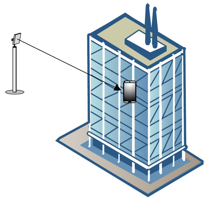
The loss will depend upon a number of factors, such as frequency, elevation angle of path at the station inside and the type of building. Measurements noted that a key factor was whether the exterior is made from:
-
Traditional materials
-
Thermally efficient materials
There can be a wide variation in losses depending upon details of the materials, the location of the station inside, the floors, furniture etc. Therefore, rather than giving a single value a statistical model was used that defines the building entry loss exceeded for a given likelihood.
The inputs are therefore:
- Frequency
- Elevation angle
- Building material
- Probability
The probability can either be entered or selected at random for Monte Carlo analysis. The elevation angle can either be entered or will be calculated from the radio path.
Recommendation ITU-R P.2108
Recommendation ITU-R P.2108 (previously described as P.Clutter) contains three component models depending upon whether:
- Terminal below representative clutter height
- Terrestrial terminal within the clutter
- One terminal is within the clutter and the other is a satellite, aeroplane or other platform above the surface of the Earth.
Height / Gain Clutter Model
This is the same model as in P.1812 and depends upon:
- Frequency
- Antenna height
- Street width
- Representative clutter height
- Clutter type
As this model is “stand-alone” it should be combined with other propagation models as considered appropriate, such as that within Recommendation ITU-R P.2001 (which does not include a clutter loss model). Note that if used with P.452 the clutter model within that Recommendation should be switched off.
The model is valid for the frequency range 30 MHz to 3 GHz.
Statistical Clutter Model
This model is purely statistical in nature, depending upon:
- Frequency
- Distance
- Percentage of locations
The model is valid for the frequency range 2 to 67 GHz and for a minimum path length of:
- 0.25 km (for the correction to be applied at only one end of the path)
- 1 km (for the correction to be applied at both ends of the path)
Elevation Clutter Model
This model gives a clutter loss that is elevation dependent. It is not a fixed value but probabilistic, so a percentage of locations (samples) value must also be given. The parameters are:
- Frequency
- Elevation angle
- Percentage of locations
This model is valid for the frequency range: 10 to 100 GHz and elevation angles from 0° to 90°.
Fixed loss Models
Const Fixed
This option adds a constant dB value to the loss. The constant is a user input.
Const Per Km
This option adds a fixed loss per kilometre of atmosphere through which the path passes.
Transhorizon loss
This allows a fixed loss to be included should the path extend beyond the radio horizon. The loss and effective earth radius can be entered by the user.
This can be combined with ITU-R P.525 propagation model which by default does not include a loss for terrestrial trans-horizon paths. Note this is not needed for earth-space links that are assumed to fail when there is no longer line of sight.
Clutter loss
The clutter loss can be entered by hand or taken from the land use database.
Extra Clutter Model
This option (found in Extra Models) defines the following options:
No Clutter Loss
.
Constant Clutter Loss
Fixed user entered clutter loss, .
P.2108 Clutter Model with zero loss short paths
If distance :
Otherwise:
P.2108 Clutter Model with linear in d interpolation
If distance :
If :
If :
calculate clutter loss at distance
P.2108 Clutter Model with log-linear in d interpolation
, P.2108 Loss
Constant Loss, Likelihood by Distance
User entered parameters:
- Fixed user entered clutter loss
- Minimum distance, do
- Exponent factor,
Calculate likelihood of line of sight, :
if distance :
if :
Then calculate clutter loss using random number :
if : if :
Other Models
Dry Air
This option calculates attenuation due to dry air using frequency dependent curves defined in CCIR Report 719 to calculate the loss on the path.
Water
This option switches on just the water vapour attenuation part of Recommendation ITU-R P.676.
Use with Define Variable Module
The Define Variable Module allows any input parameter to be specified for each time step as being selected from a distribution or defined from set of values.
This can be used to extend the propagation models further – for example to specific distributions such as Rayleigh or log-normal fading or user entered distributions.