Maritime
This section contains the following examples:
ESV Interference Area
| Action: | None |
| Modules used: | Terrain, IDWM |
| Terrain regions: | Seattle Area |
| Frequency band: | C |
| Station types: | GSO Satellite, Earth Stations, Fixed Stations, Maritime |
| Propagation models: | Free space, ITU-R Rec.P.452, ITU-R Rec.P.530 |
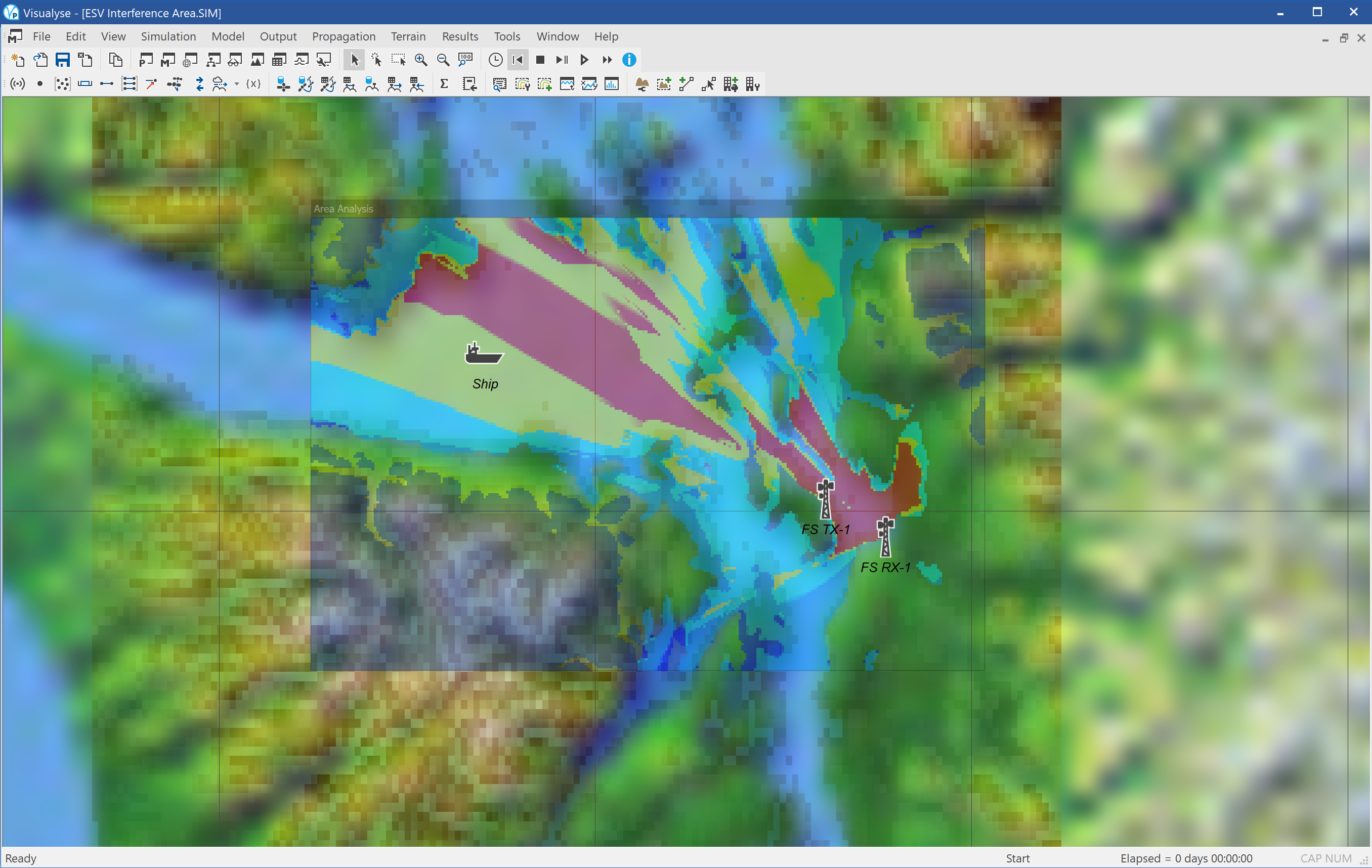
This example shows locations where an Earth Station on Vessel (ESV) transmitting up to a GSO satellite in C band could cause interference into co-frequency point to point fixed links. This analysis could also be used for adjacent or guard band operation or to calculate interference into point to multi-point fixed services.
The simulation has been configured to calculate the interference from an Earth Station into a fixed service receiver taking into account the effect of terrain using the ITU-R Rec.P.452 propagation model. This has been configured with a percentage of time of 0.216% based upon:
Required probability of interference = 0.001%
Number of ships / day = 4
Time spent at each pixel = 100 seconds
Probability ship active at pixel = 1/216
Propagation probability used = 216 * 0.001 = 0.216%
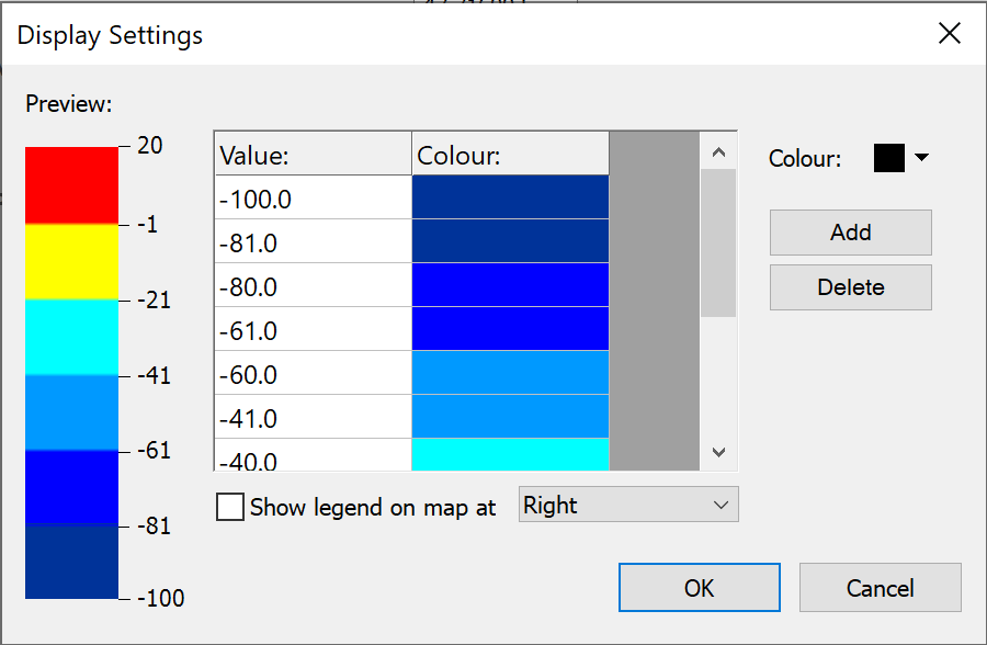
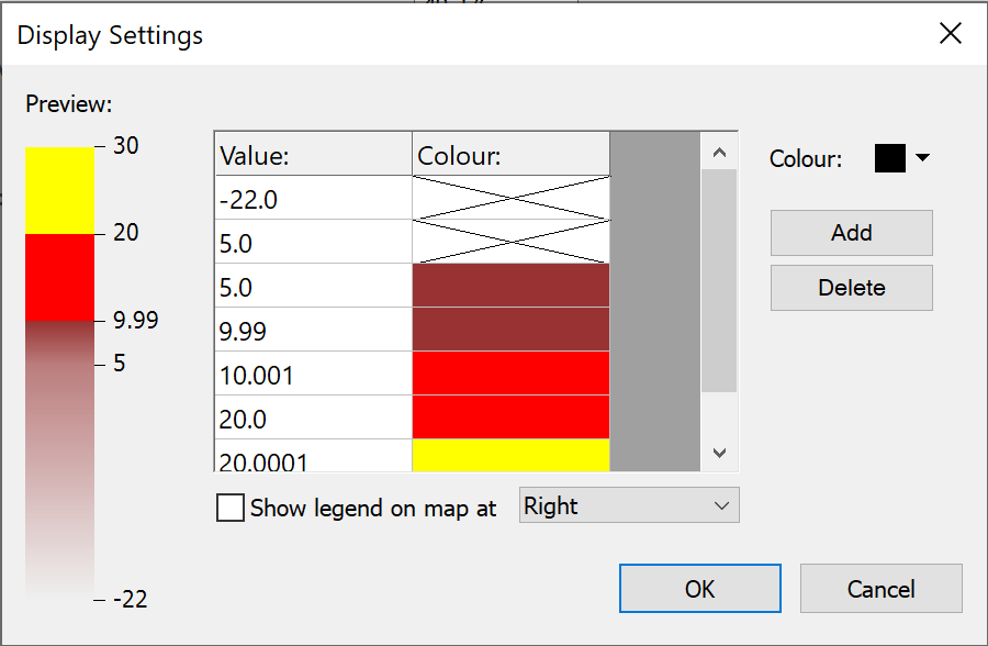
The window above shows the I/N that the ESV would cause colour coded as follows:
GSO ES on ship entering Seattle Port into FS
| Action: | Run simulation |
| Modules used: | Terrain, Define Variable, IDWM |
| Terrain regions: | Seattle Area |
| Frequency band: | C |
| Station types: | GSO Satellite, Earth Stations, Fixed Stations, Maritime |
| Propagation models: | Free space, ITU-R Rec.P.452, ITU-R Rec.P.530 |
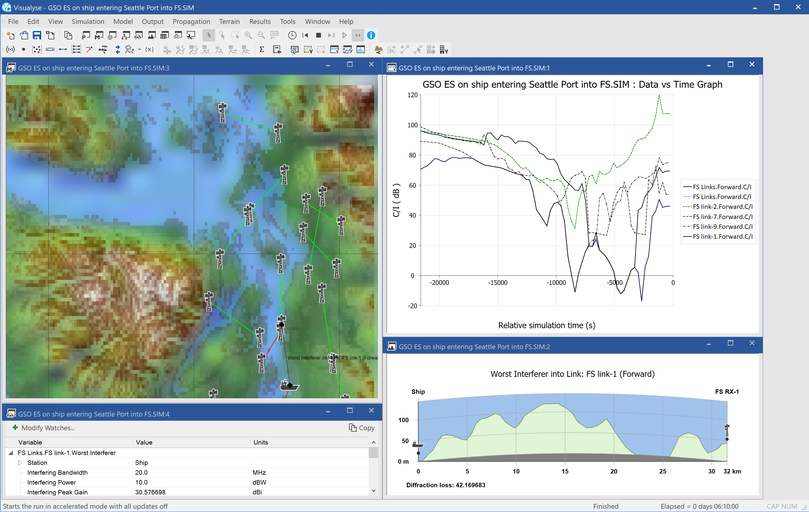
This example considers interference from the uplink from an Earth Station on a Vessel (ESV) into terrestrial point to point fixed service (FS) links operating in the vicinity. The ESV is approaching the port of Seattle while transmitting and the amount of interference it could cause will depend upon the locations of the ship and FS receivers.
The simulation has been configured with the movement of the ship defined using a series of way points. The interference from the ship at the fixed service receiver has been calculated taking into account the effect of terrain using the ITU-R Rec.P.452 propagation model. The wanted signal of the FS link is calculated taking into account fading due to multi-path and rain as in ITU-R Rec.P.530.
The screen shot above shows four window open:
- Mercator map view (top left), shows the locations of the FS stations, the ship, the terrain, and the various links, which go red when they suffer interference
- Quick graph (top right), shows how the C/I of some of the links varies as the ship progresses up the channel
- Watch window (bottom left), shows the worst single interferer’s link budget for the one of the FS links
- Path profile window (bottom right), shows the terrain between the ship and the receiver on one of the FS links
MRCC Coverage
| Action: | None |
| Modules used: | Terrain, IDWM |
| Terrain regions: | SW England |
| Frequency band: | VHF |
| Station types: | Maritime |
| Propagation models: | ITU-R Rec.P.1546 |
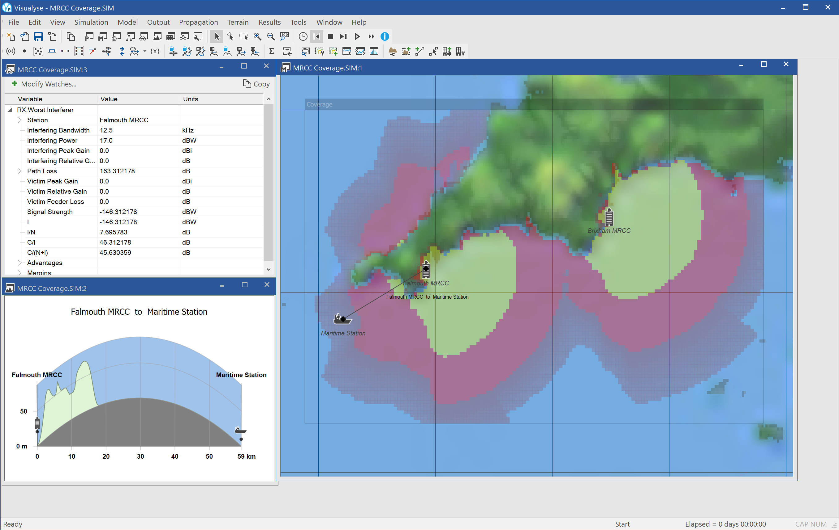
This example shows an example of Visualyse Professional the coverage of a maritime VHF voice communication. It calculates the C/N for a 12.5 kHz voice carrier operating on channel 16 around 156 MHz
Two Maritime Rescue Co-ordination Centres (MRCC) are modelled and the ship is assumed to transmit at 15W i.e. 17 dBW at a height of 10m above sea level, while the coast guard antenna is at a height of 20m above the local terrain.
The prediction is made using ITU-R Rec.P.1546 propagation model and the Area Analysis shows the C/N coloured according to the following scale:
The screenshot shows three windows open:
- Mercator map view (right) showing the locations of the coast guard centres, a ship test point, and the predicted coverage
- Watch window (top left) showing the link budget for the link between the ship and the nearest coast guard
- Path profile (bottom left) showing the terrain between the ship and the nearest coast guard.
This type of analysis could be used to:
- Ensure there is coverage on channel 16 of the major shipping routes
- Identify where there could be re-use of channels between marinas or for in-port communications
- Analyse the options to move to 4 or 6 kHz channels
- Analyse the ability to re-use channels for in-land applications