Military
This section contains the following examples:
Missile telemetry with jamming
| Action: | Run simulation |
| Modules used: | None |
| Terrain regions: | None |
| Frequency band: | X |
| Station types: | Non-GSO Satellite, Earth Stations |
| Propagation models: | Free space, ITU-R Rec.P.676 |
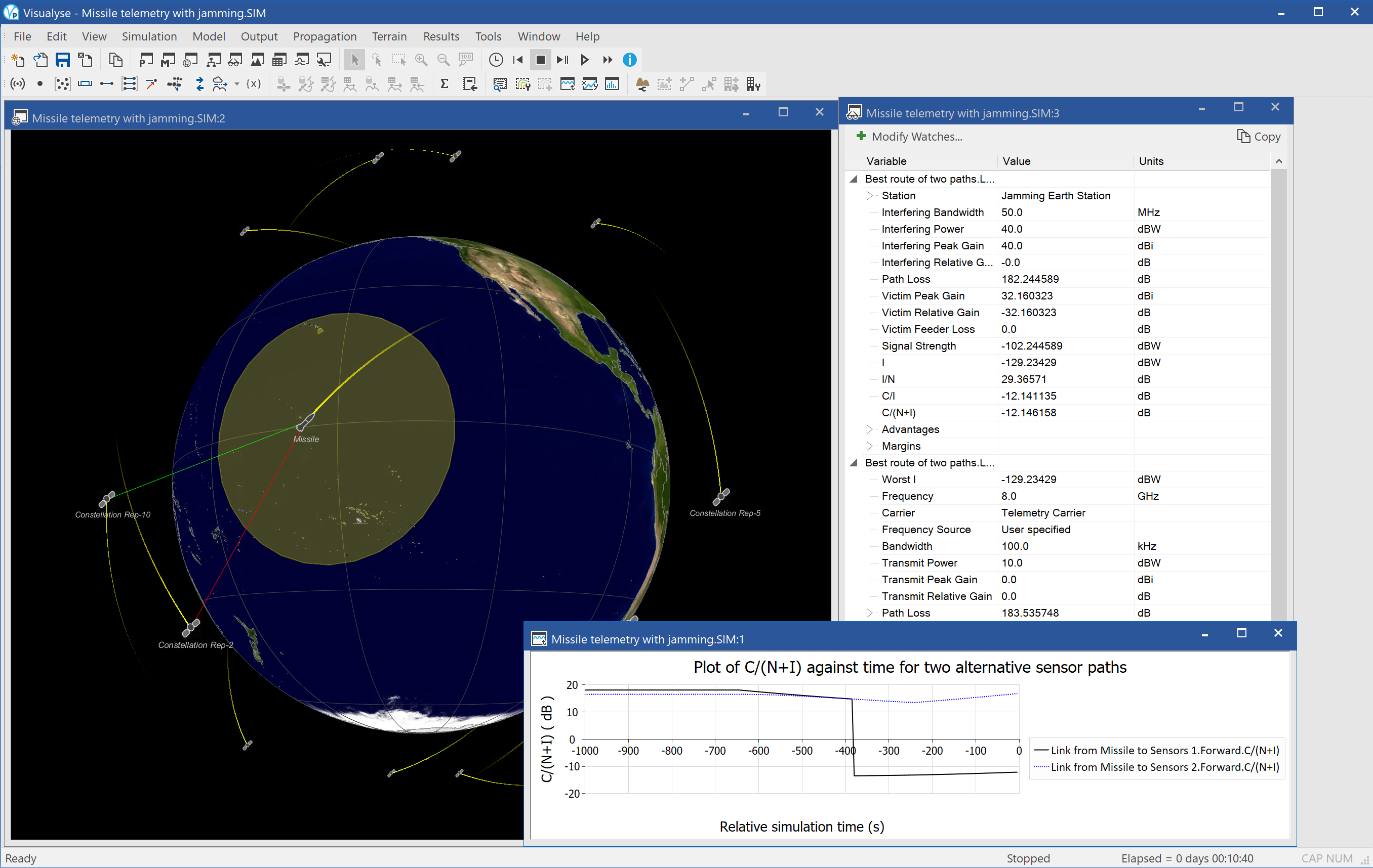
This example shows an example of Visualyse Professional modelling jamming. This is specialised form of interference that is deliberately generated to cause loss of service rather than (as is usually the case) unintentional.
A number of jamming scenarios could be considered – indeed all the interference simulations in this document could be considered jamming if the motivation was hostile. This simulation shows an exercise where susceptibility of a missile’s telemetry to jamming was being tested.
A missile is launched on a test trajectory across the Pacific Ocean, relaying data to ground via a network of satellites at X-band. In the exercise jamming station try to interrupt collection of data with a 10 kW transmission. The main mitigation method to the jamming attack is to switch to an alternative routing i.e. select a back-up satellite.
The simulation is configured with three views open:
- 3D view (left) showing the satellite constellation, the missile, the tracks, the jamming ground station, and the beam footprints
- Watch window (top right) showing the link budget of the wanted signal and the link budget of the jamming signal
- Quick graph (bottom right) showing how the C/N of the first and second preference links taking into account the effects of jamming.
UAV demo
| Action: | Run simulation |
| Modules used: | Define Variable, Terrain |
| Terrain regions: | Afghanistan |
| Frequency band: | Ka, V, S |
| Station types: | GSO Satellite, Earth Stations, Fixed Stations, Aeronautical stations |
| Propagation models: | Free space, ITU-R Rec.P.676, ITU-R Rec.P.452 |
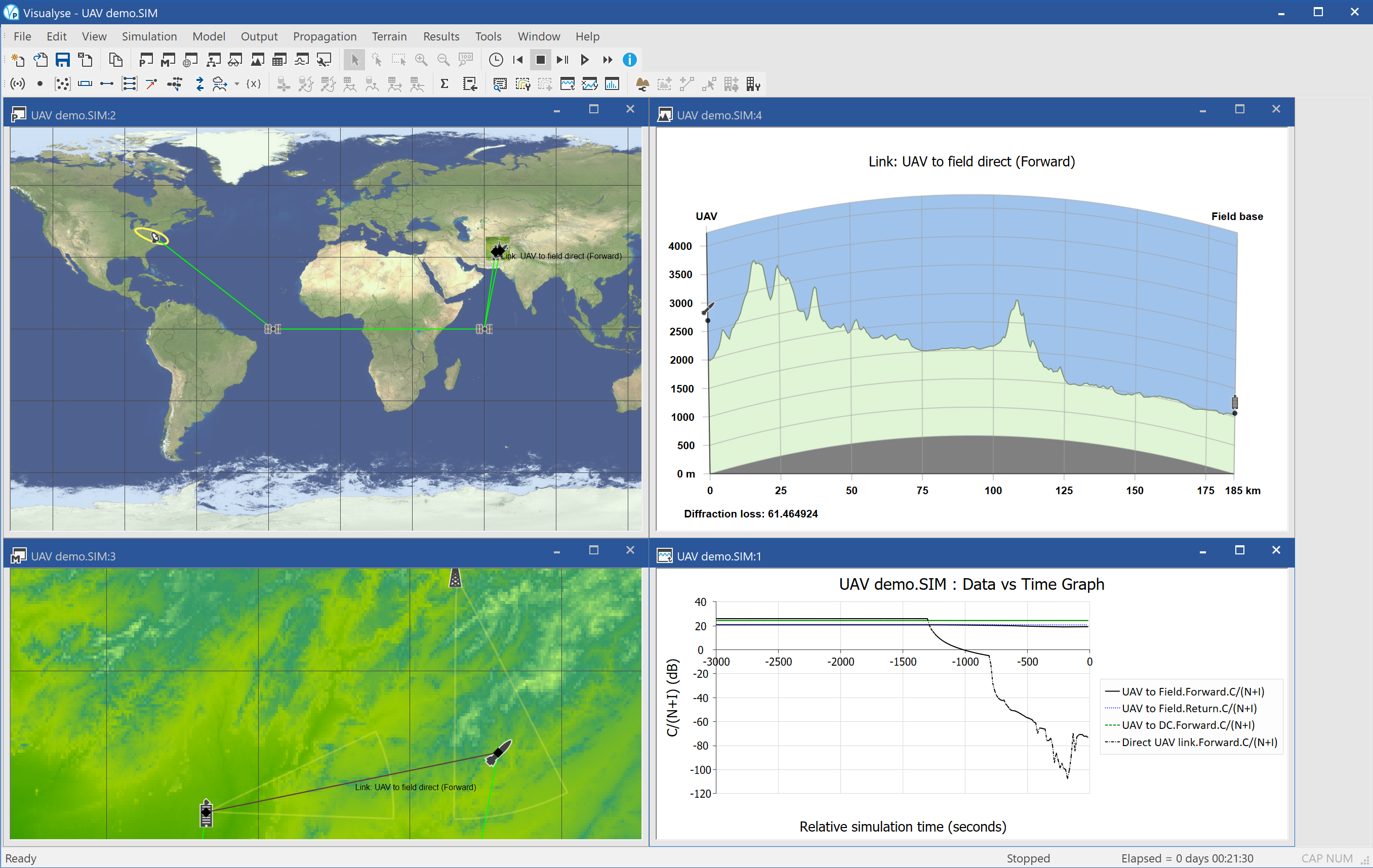
This example shows an example of Visualyse Professional modelling unmanned aerial vehicle, i.e. a UAV, including jamming.
The UAV is sent on a mission to observe targets in the hills of Afghanistan. Its flight path is defined by a set of way points in (latitude, longitude, height). As it enters the mountainous region it climbs and then descends into valleys.
Initially the communication is with the local field base: however soon the UAV is beyond range and instead a satellite link is used. The model also includes the complete end-to-end link back to the operations room in Washington DC. A range of frequency bands are used, including Ka for the UAV to satellite, V for the inter-satellite, and S for the field base to UAV.
At times during the mission the UAV suffers from jamming, and so the C/N is degraded. The model includes realistic modelling of propagation of wanted and interfering signals over terrain using ITU-R Rec.P.452 and a terrain database.
The simulation is configured with four views open:
- Plate Carrée map view (top left) showing the satellites routing the communications back to Washington DC
- Mercator map view (bottom left) showing the location of the field centre, the terrain, the UAV, the jamming station, and various communications links
- Terrain path profile view (top right) showing the terrain between the field base and the UAV
- Quick graph (bottom right) showing the C/Ns for the direct link to field base and satellite link