Fixed Terrestrial Stations
When you create a new fixed terrestrial Station, the dialog shown below will appear.
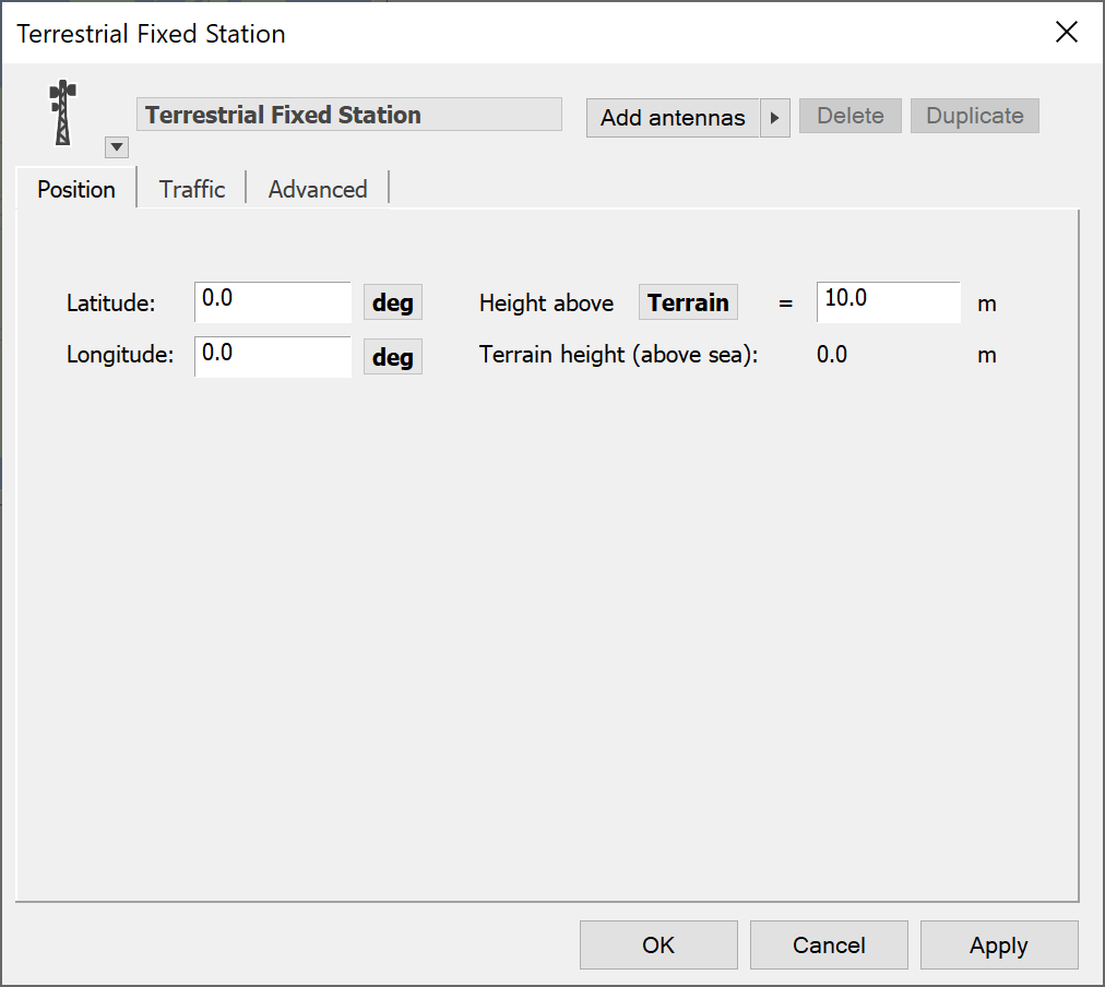
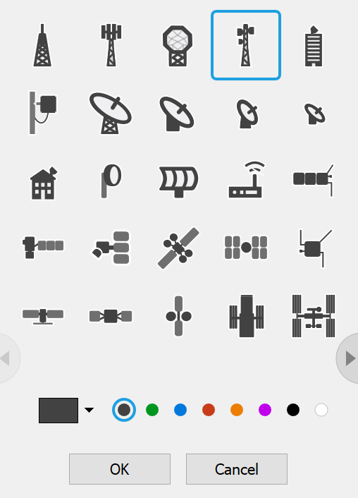
The Station icon can be changed by clicking on the small black arrow by the side of the icon. This produces a drop-down menu from which a new icon can be selected.
The tabs shown when this station is created are Position, Traffic and Advanced.
Position
The position tab allows you to set the location of the Station.
You can change the latitude and longitude of the Station. Clicking on the units will produce a popup menu from which you can pick the units that are appropriate.

If you select degrees, minutes, seconds, the format is:
[N/S/E/W] DD:MM’SS.SS”
You can choose whether to specify the height of your Station above the terrain or above sea level. If you have any terrain data in this simulation the terrain height at that location is displayed.
Adding and Managing Antennas
A Station can have multiple Antennas. The parameters for each Antenna are presented on a separate tab. By default, a Station is created with one Antenna.
An example Antenna tab is shown below.
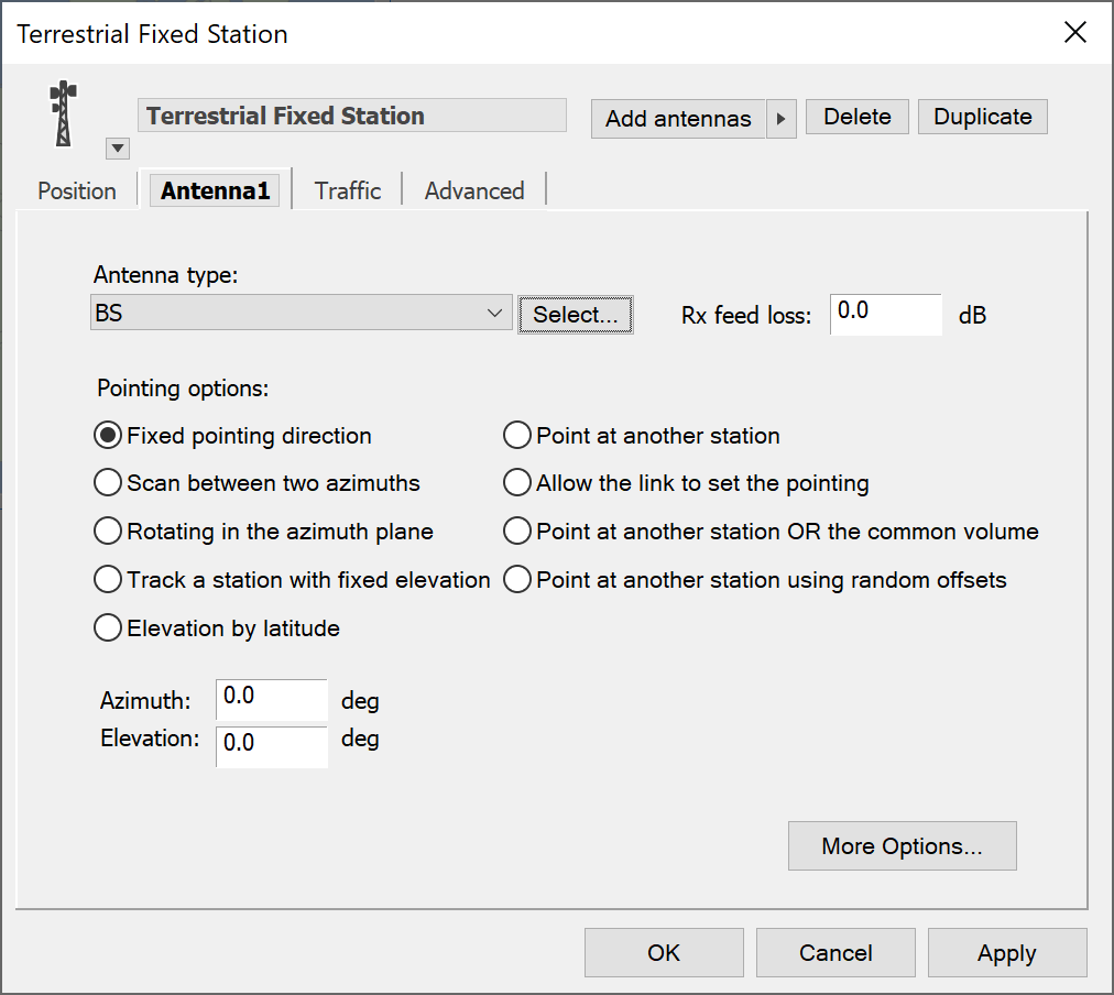
The parameters for the selected Antenna are:
- Type – which of your library of antenna models to use for this station
- Feeder loss – what is the loss in dB due to the feed from the antenna to the receiver (not transmitter – see Technical Annex for more information)
- Pointing options – how is the pointing of this antenna determined.
Click the Select button to change the type of Antenna. This will show a dialog from which you can choose one of the new Antennas you have created.
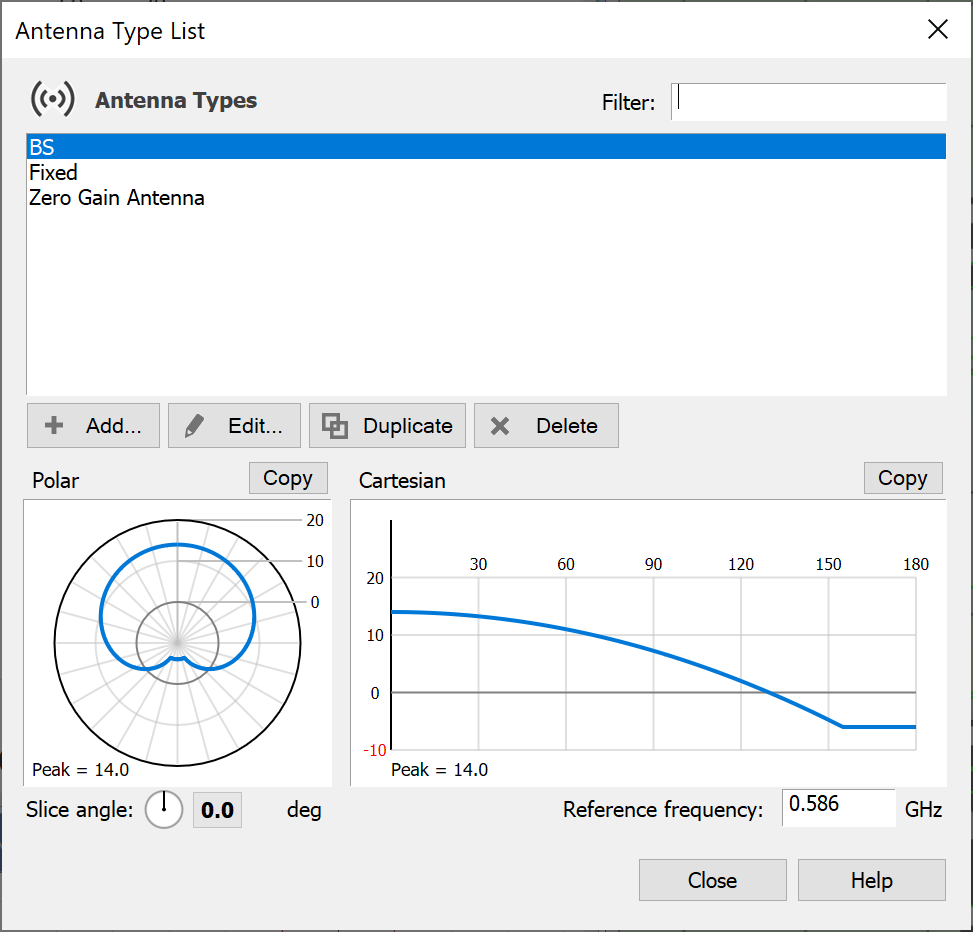
Choosing an Antenna Type means that the Station will use the characteristics of the Antenna as defined in the Antenna list. An important point is that if the Antenna in the Antenna list changes, all Stations that use that Antenna will change accordingly.
Antenna Pointing
They presented as a set of radio buttons and the options are described in Antenna and Beam Pointing. Clicking the required method reveals the parameters needed to fully define it.
First you decide how you want to point your Antenna, and then you set the required parameters for the pointing option you have chosen.
More options
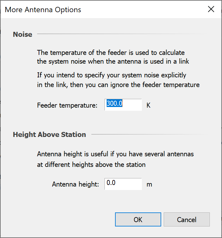
The ‘more options’ button allows you to specify Antenna temperature and the Antenna height.
Feeder temperature is needed if you are going to let Visualyse calculate system noise from the component contributions due to the Antenna, feeder and receiver. The choice of how to calculate system noise is made in the Link dialog – you have the option simply to enter the system noise directly in Kelvins, and if you are going to do this there is no need to enter the Antenna noise.
Antenna height is the height above the Station, and has some influence on some propagation models and, of course some influence on the simulation geometry.
Managing Multiple Antennas in a Single Station
Management of multiple antennas is very similar to that of beams on the Antenna dialog (Managing Beams). To add multiple Antennas, click on the black arrow to the right of the Add Antennas button.
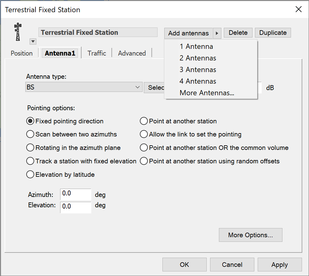
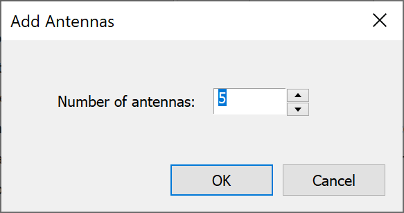
From this menu, you can choose how many Antennas you want to add to your Station. There are options for quickly adding up to four Antennas at a time. If you want more than four Antennas, click the More Antennas option. A dialog box will appear allowing you to specify the exact number of Antennas you require.
New Antennas appear as new tabs. If there are more Antennas than will fit across the dialog, scroll buttons will appear to allow you to access the extra tabs.
Duplicating and deleting functions work on the currently selected Antenna. If you duplicate, the new Antenna becomes the active selection. If you delete, the next Antenna becomes the selection (unless you delete the last Antenna in which case the previous Antenna becomes the active selection)
Naming Antennas
Antennas are automatically given names by the software. However, you can give your Antennas more meaningful names, and this practise is encouraged because good naming makes complex models easier to understand (especially if you revisit them at some time in the future and need to remember what you were doing)
You rename the antenna by interacting with the name on the tab directly. It works in the same way as when you change the Station name.
When the mouse passes over the Antenna name the cursor changes to a caret, 
If you click on the name, it changes to an edit box so that you can alter it. This is shown below.

Typing a new name causes the tab to automatically resize. Click away or hit Return to finish editing.

You can only do this with the selected Antenna. To change the name of another Antenna, you need to select it first.
Advanced Option
The advanced tab incorporates the Station coordinate system parameters and attitude parameters relating to the station reference frame.
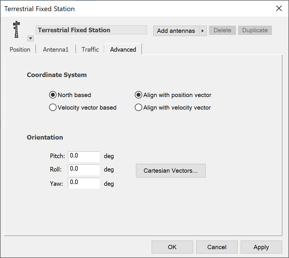
For a description of the effect of changing the coordinate system reference, and for definitions of the Station azimuth and elevation see the Technical Annex.
Parameters relating to the reference frame definition and to the station attitude are editable here.
Click the ‘Cartesian Vectors’ button to bring up the definitions of the vector position and velocity of the station.
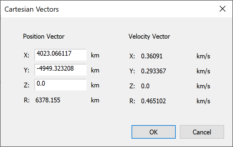
You can edit the vector components directly here – it is unlikely that you will ever want to do this, and we recommend that, unless you know exactly what you are doing, do not change these fields.
Traffic Modelling
Traffic won’t appear on the Station dialog at all unless your installation has the traffic module. If traffic is enabled, the traffic tab will appear as shown below.
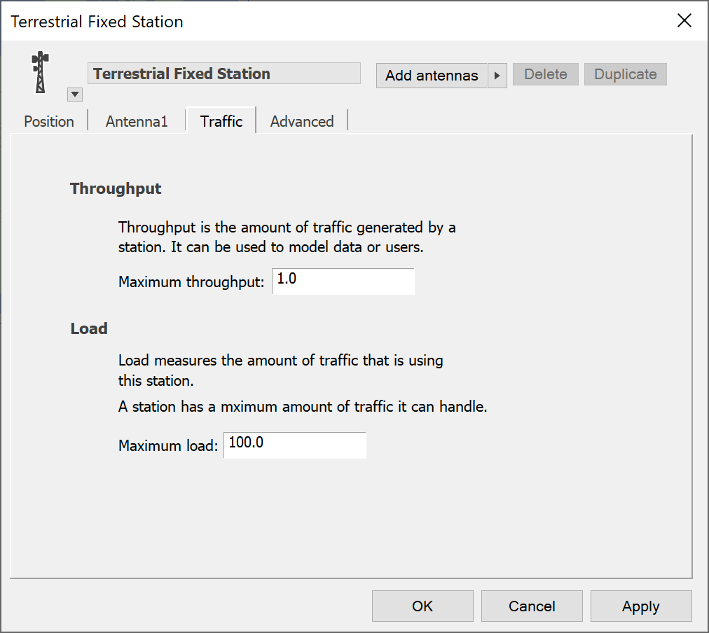
For details of how to use the traffic module, please refer to the Module User Guide. Note the maximum load field can be used by the Population Data processing as described in Service Area Wizard.