Interference Paths
The interference scenario is defined in terms of any number of Interference Paths. An interference path consists of a wanted Link or Link Group and a number of interfering Links or Link Groups.
All Links defined in the simulation are available for selection as interferers.
Where multiple Links are defined as interferers, the aggregate interference power is automatically calculated.
The Interference Paths dialog can be invoked in the normal ways, i.e.
- Via the toolbar icon
- Via the Model menu
- By right mouse click in the Model view
There are three parts to the dialog:
- Select the Victim Links
- Select the Interfering Links
- An advanced tab where you define the interference calculation options
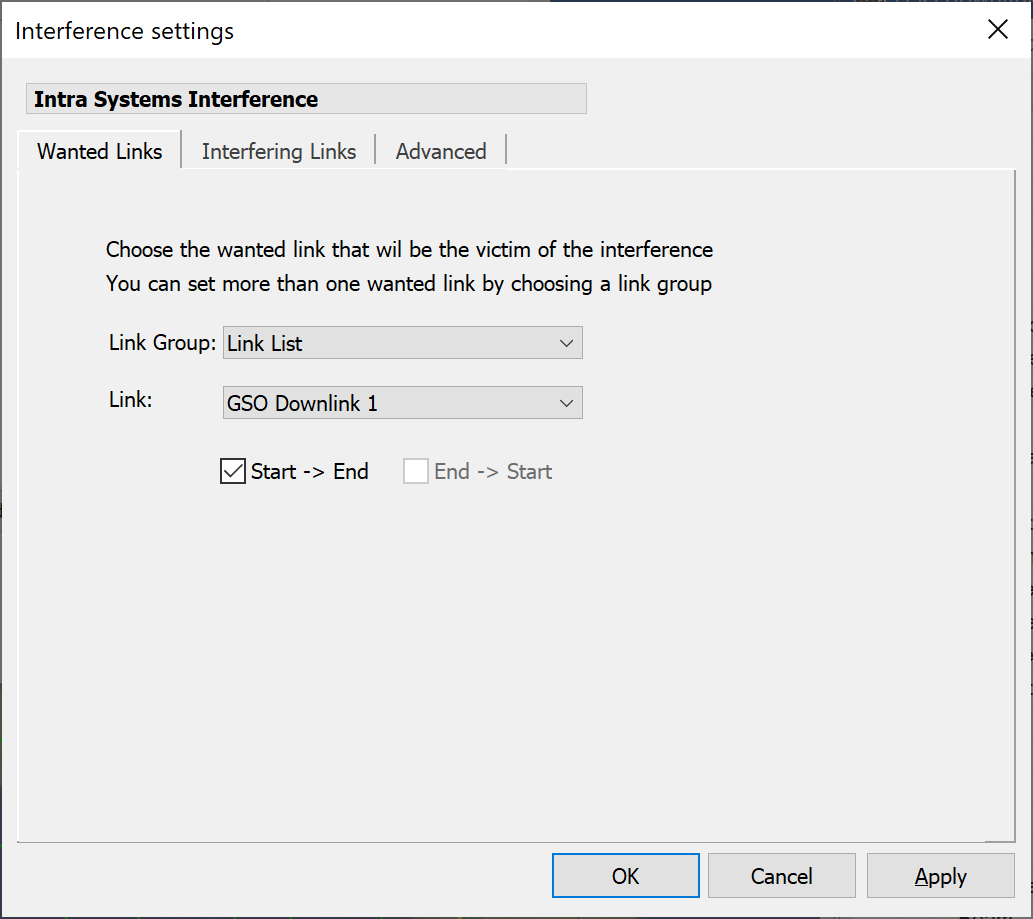
Select the Victim Link(s)
Select either a Link Group or a Link from the Link List. If you select a Link Group only, Interference paths will be set up for all Links in that group.
Select the Interfering Link(s)
On the interfering links tab, the list off all potential interferers is displayed in the left-hand pane. Any Links or Link Groups currently selected as interferers are shown in the right-hand pane.
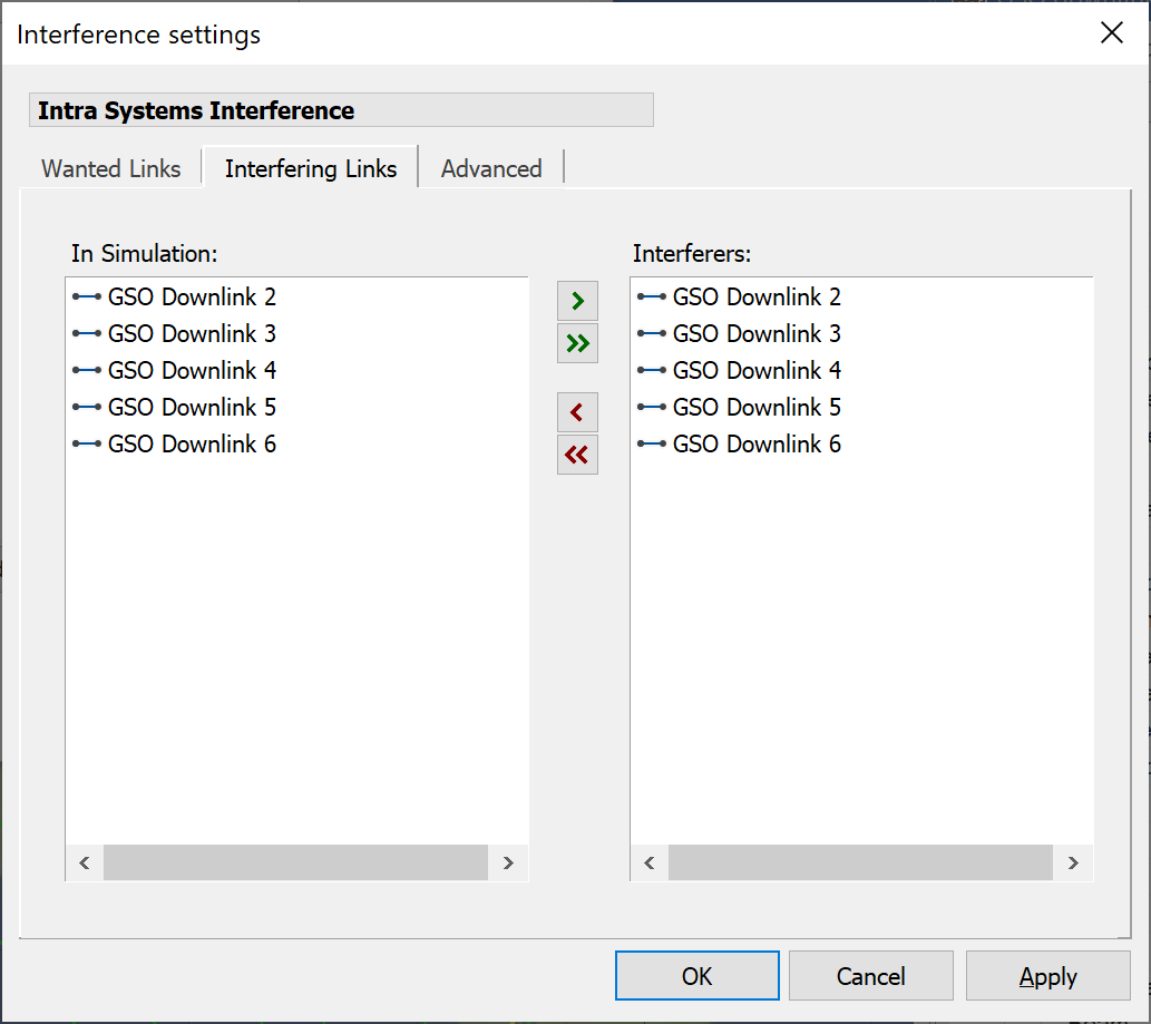
Where a Link or Link Group is bi-directional, both directions (start – end and end start) are given as options.
To include a Link Path as an interferer, move it to the right-hand pane using the arrow buttons.
Advanced Interference Path Options
The Advanced tab includes several parameters that have an effect on the interference calculation.
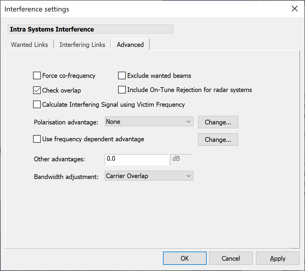
Each calculation option is described below
Force Co-frequency
Checking the “Force Co-Frequency” box forces all interfering Links to be co-frequency with the wanted Link, for this interference path only. This option is used for worst case analysis.
An example use of this option would be if many interfering Links have been entered with different frequencies according to some channel plan, and a worst-case analysis is required. The worst-case analysis may not include the channel plan. Forcing cofrequency would allow the existing Links to be used without losing the channel plan data.
This option should not really be used to scale systems from, say Cband to Kuband. The adjustment is only applied when the bandwidth overlap factor is calculated. Therefore, frequency Antenna characteristics and pathloss would not be accounted for correctly.
Check Overlap
Where out of band emissions are of interest, it may be that you want to include interferers that have no frequency overlap with the wanted carrier. In combination with frequency off-set advantage, the Check Overlap option can be used to model the effect of out of band or spurious emission.
If Check Overlap is set then all interferers must have overlap in their allocated bandwidths to be included in the interference calculation. If it is not set then interfering paths will be included whether or not they have overlap in bandwidth.
Exclude Wanted Beams
This option is useful when analysing intra-system interference and considering a Link Group as the wanted element in the interference path.
In this case the wanted Links would also be used as interferers i.e. you can select the same Link Group as the interfering element.
With the Exclude Wanted Beams option selected, interference into a particular wanted Link would be considered from all the other Links in the group, but not from any links using the transmit beam of the wanted Link.
Include On-Tune Rejection for Radar Systems
If this field is activated and the relevant Carriers have the radar fields defined, then the On Tune Rejection (OTR) will be calculated according to ITU-R Rec. M.1461 “Procedures for determining the potential for interference between radars operating in the radiodetermination service and systems in other services”
Calculate Interfering Signal using Victim Frequency
When using the IMT-MODEL gain pattern (e.g. for IMT-2020 or 5G studies) there can be a different gain pattern for co-frequency and non-co-frequency scenarios. The way to define this in the Antenna Type is described in IMT-Model Non-Co-Frequency Parameters.
By default the interfering signal is always calculated using the centre frequency of the interfering link. However to activate the non-co-frequency gain patterns it is necessary to use the centre frequency of the victim link.
This can be achieved by checking the option “Calculate Interfering Signal using Victim Frequency”.
If this is enabled then the interfering signal will be calculated using the victim centre frequency and hence allow the antenna type to identify if the path is co-frequency (to the IMT-MODEL antenna) or non-co-frequency.
Note that this will not affect other calculations, in particular the mask integration adjustment or NFD.
Polarisation Advantage
When polarisation advantage is included, the interfering power level may be reduced by a set amount.
The options available in the drop-down list are:
- None
- ITU Radio Regs
- User Defined
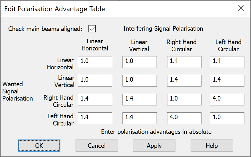
The table below shows the numerical ratios to be used for polarisation isolation between two carriers when the Radio Regulations option is selected.
When User Defined is selected, this table is available for editing via the dialog below. By default, the advantage is only applied when there is main beam to main beam coupling between the wanted receiver and the interfering transmitter. The same user defined table is used for all Links
Frequency Offset Advantage
It is possible to define a dB advantage relating to the offset of the centre frequencies of the wanted and interfering carrier. The effect is to reduce the interfering carrier level or (equivalently the wanted receiver response) by a number of dBs at each defined frequency offset.
This could be used, for example, to model the out of band interference of a narrow band carrier into a wide band receiver with a known filter characteristic. The filter characteristic would be reflected in the off-set advantage.
Details of the effect on the interference calculation are given in the Technical Annex.
If multiple interferers are defined, they will all be affected by the frequency off-set advantage.
To use this advantage make sure the Use Frequency Dependent Advantage’ box is checked. The characteristic shape can be edited by clicking the Change button. The following table will then be available.
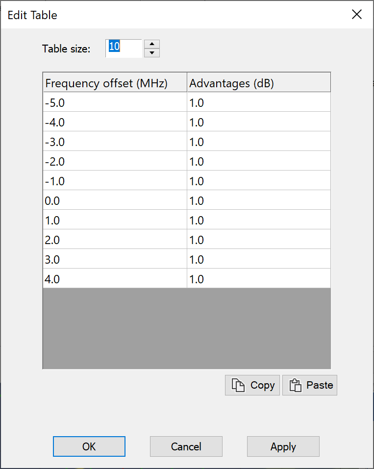
You edit the table directly or use Copy/paste of data from other applications.
Other Advantages
The Other Advantages field can be used to specify a dB value to be added or subtracted from each interfering signal. This may be used in a number of ways. For example, a real value for polarisation advantage might be known from Antenna performance data and from the polarisation plan definition. The polarisation isolation would be entered as a positive number in this field.
Alternatively, this factor could be used to model carrier fading (when C/I is being considered) by entering a negative number in this field. The negative number may be equal to the expected rain fade for example.
Bandwidth Adjustment Factor
The various possibilities for bandwidth adjustment factor determine how the overlap between the wanted and interfering carrier is taken into account.
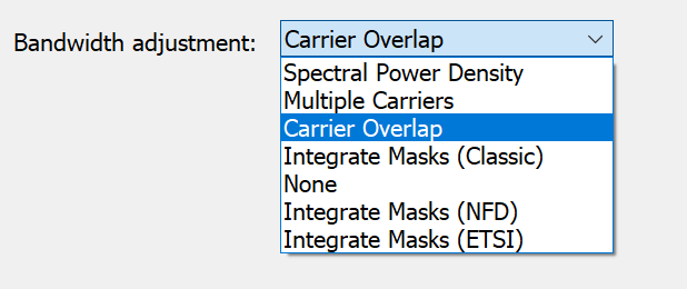
The options available are:
- Based on spectral density - ignoring bandwidth factors and taking the ratio of spectral densities as the C/I
- Assuming multiple interfering carriers - where the interferer has a narrower bandwidth than the wanted carrier, interferers are stacked into the wanted carrier bandwidth. If the interferer has a wider bandwidth than the wanted carrier then the overlap of the two is calculated.
- Based on overlap of a single carrier - this explicitly calculates the proportion of the interferer that falls into the wanted bandwidth
- Integrate masks – calculates the Net Filter Discrimination (NFD) based upon the TX and RX masks. There are a number of alternative NFD calculation methods as described in the Technical Annex.
- None - the ratio returned in this case is just the ratio of the total received powers of the wanted and interfering carrier at the wanted receiver.
Each option is described in detail in the Technical Annex.