Link Group Created Empty
Empty Link Groups are used as containers for Links. When there is a large number of Links in the simulation, it becomes easier to manage them using Link Groups. At the basic level, you can put all your victim links into one group and all your interferers into another.
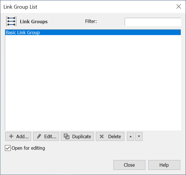
To create an empty Link Group click ‘add’ in the Link Group List (accessible via the Model menu or via the Link Group icon in the toolbar). Then select the first option – Link Group.
A new Link Group, default name Basic Link Group will appear in the Link Group list.

Double click on the Link Group or click the Edit button to edit the Link Group.
The edit dialog has two tabs:
- The Links Tab – add and remove Links from the Link group here.
- The Advanced tab – to override simulation defaults for statistics collection and Link graphical display characteristics here.
Above the tabs is the Link Group name – by default it will be Basic Link Group (or Basic Link Group 1, 2 etc). You can (should) change the name by click on it with the mouse.
The Links Tab
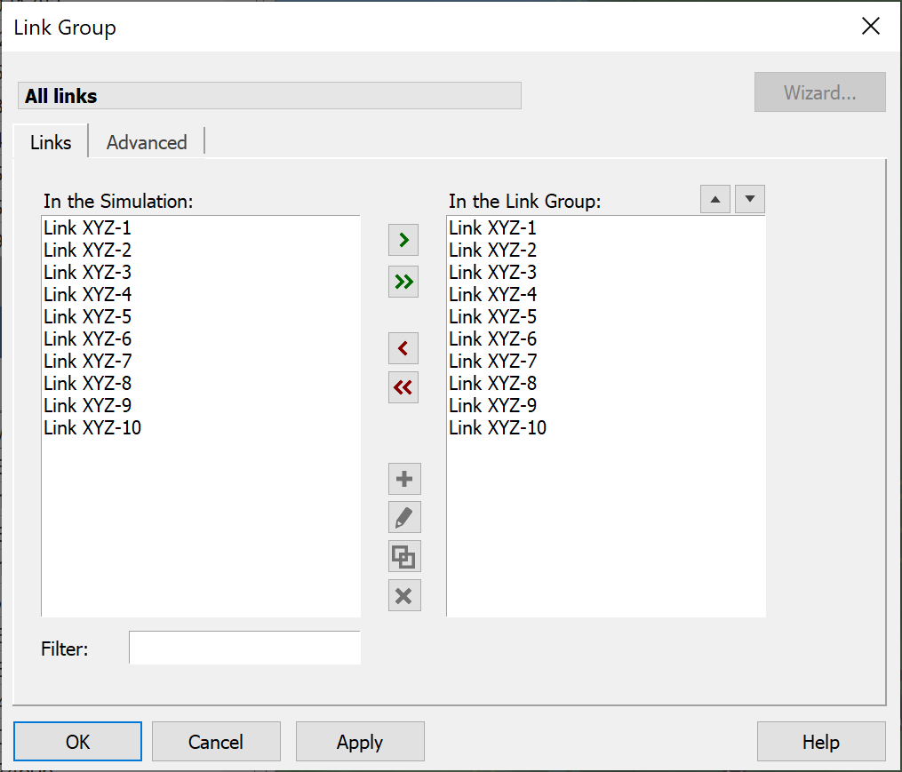
The Links tab is shown in the figure below. The function of this tab is to select Links from the simulation for inclusion into the Group and also for ordering the Links within the Group.

The left pane shows all the Links defined in the simulation and the right pane shows those that are included in the Link Group.
Transfers to and from the Group are via the  and
and  buttons.
Select the Links you want to transfer by highlighting and then press the  button to include or remove them from the Group. Alternatively, the
  button will include or remove all the stations.
Under certain circumstances, the order of Links within the Group can be important – for example, if the Links are Dynamic and ‘competing’ for resources such as Antennas and Beams, those at the top of the list will be processed first.
To promote or demote a Link within the list, select the Link in the right pane and click the  button to promote and the
  button to relegate.
Filter the left pane contents using the filter edit field.
The Advanced Tab
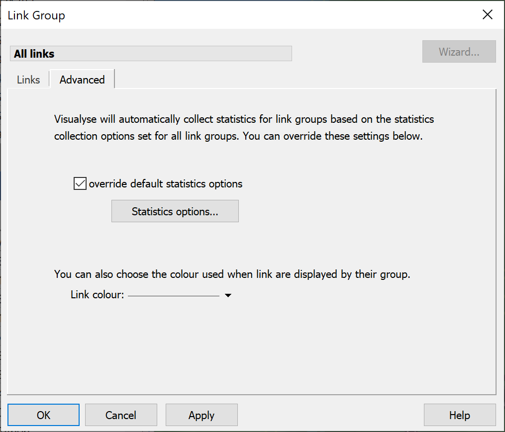
The Advanced tab is used to override simulation defaults for Link colours and for the statistics that are collected.

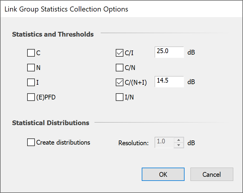
Statistics to be collected are defined for the simulation as a whole via the Output menu. This is where you tell Visualyse to collect and or all of C, N, I, C/N, C/N+I, I/N and PFD statistics, and where the threshold ratios are set. For each Link Group you can change the parameters collected and/or the thresholds.
To override the simulation settings, check the ‘Override default statistics options’ and click the statistics option button. You will see the Statistics Collection Options tab.

Parameters that are selected in the simulation defaults (see the Overview section of this User Guide) will be checked – if you don’t want statistics on those for this Link Group then uncheck them here. Check any additional parameters you want to analyse and set the threshold levels.
Decide whether you want to generate histograms and the bin size (resolution) for the histograms.
Links can be displayed on map and 3D views either according to the status of the Link (in terms of meeting threshold C/X levels) or according to display properties set here. Click the ‘Link Colour’ button and select the colours to use when displaying the Links in this group.