Carriers
This section describes how carriers are modelled and defined in Visualyse.
Carriers are where you define bandwidths, polarisation, and other characteristics of the signal spectrum together with some aspects of the signal structure.
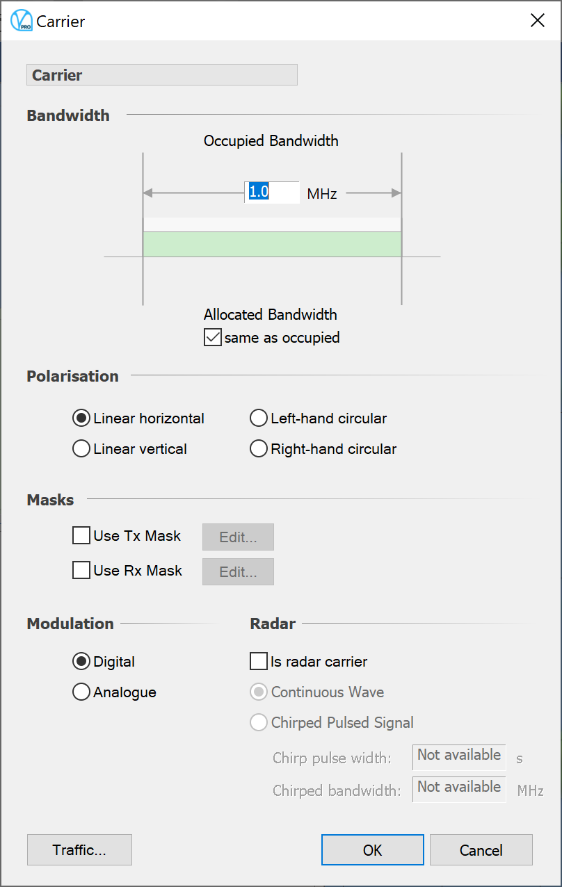
Things which are addressed in the carrier dialog are:
- Allocated bandwidth
- Occupied bandwidth
- Polarisation
- Receive and transmit masks
- Digital/analogue modulation
- Is the carrier a radar carrier
- Radar carrier parameters
The edit Carrier dialog is shown in the figure below.

The dialog is made more complex by the fact that the effect of bandwidths and spectral masks varies depending on choices you will make later when you set up the interference. Put simply – you need to decide how to deal with interference in cases where bandwidths can be very different and also how to deal with the out of band emissions implied by non-trivial spectral masks. This is covered further in more on this in Interference Paths.
Spectrum Masks and Net Filter Discrimination
Version 7 introduced the TX and RX masks which together can be used to define a net filter discrimination (NFD). The details of the calculation are given in the Technical Annex, but the idea is that you define the data that represents the spectral mask for in band and out of band emission/response for this carrier when used in a transmitter or receiver.
Data are entered in a table that gives the relative level of the mask compared to the peak, at any number of frequency off-sets from the centre frequency.
Later, when you define a victim and an interferer, Visualyse will do a numerical convolution and work out the Net Filter Discrimination over the whole overlapping band. You can also get Visualyse Professional to use the bandwidth calculated from the transmit spectrum mask in the NFD calculations.
The carrier type can be specified as digital or analogue – if you are modelling multiple hop systems and looking at end-to-end performance this will have a significant effect. Noise on a series of analogue links is additive, whereas on digital regenerating links the noise in the system is determined by the worst single link.
The polarisation of the carrier can be defined as left or right circular, linear vertical or linear horizontal. This can be considered when calculating interference levels depending on choice made in setting up the Interference Path object (Interference Paths).
If you have the Visualyse Traffic Module then other carrier parameters, accessible via the Advanced button, will also be relevant. The significance of these parameters and the use of different load methods are described in the Module User Guide.
The radar parameters are used in the interference path to calculate the On Tune Rejection (OTR) according to ITU-R Rec. M.1461 “Procedures for determining the potential for interference between radars operating in the radiodetermination service and systems in other services”.